





Description
Key Technical Specifications
| Parameter | Value / Specification |
| Part Number | SPASI23 |
| Module Type | Analog Input (AI) |
| Number of Channels | 16 single-ended or 8 differential |
| Signal Compatibility | Thermocouple (TC), millivolt (mV), RTD, High-Level Voltage/Current |
| A/D Resolution | 16-bit high-precision analog-to-digital conversion |
| Accuracy | \pm0.1\% of full scale (typical) |
| Isolation Voltage | 1,500 V RMS galvanic isolation between channels and system logic |
| Power Consumption | 2.5 W nominal |
| Input Supply Voltage | 24 V DC backplane derived |
| Dimensions (H x W x D) | 360.68 mm x 269.24 mm x 73.66 mm |
| Weight | 0.771 kg |
Product Introduction
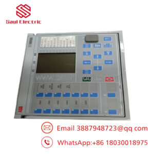
The ABB SPASI23 is a high-density, 16-channel analog input module designed for the Harmony Rack series within Symphony Plus and legacy Infi 90 Distributed Control Systems (DCS). This module interfaces directly with critical process instrumentation, accepting a diverse mix of field inputs including thermocouples, millivolt signals, RTDs, and high-level analog signals. By executing precise onboard signal conditioning and 16-bit digitization, the board delivers highly accurate process variables directly to the rack controllers.
Plant operations prioritize the SPASI23 for control loops where multi-sensor monitoring is essential, such as turbine temperature matrices, boiler heat zones, and chemical reactor profiling. Its built-in channel isolation and dedicated filtering circuits shield the control layer from harsh industrial field noise, ground loops, and high-common-mode electrical transients. The multi-type configuration flexibility eliminates the need for external signal transmitters, reducing cabinet footprint and hardware lifecycle costs.
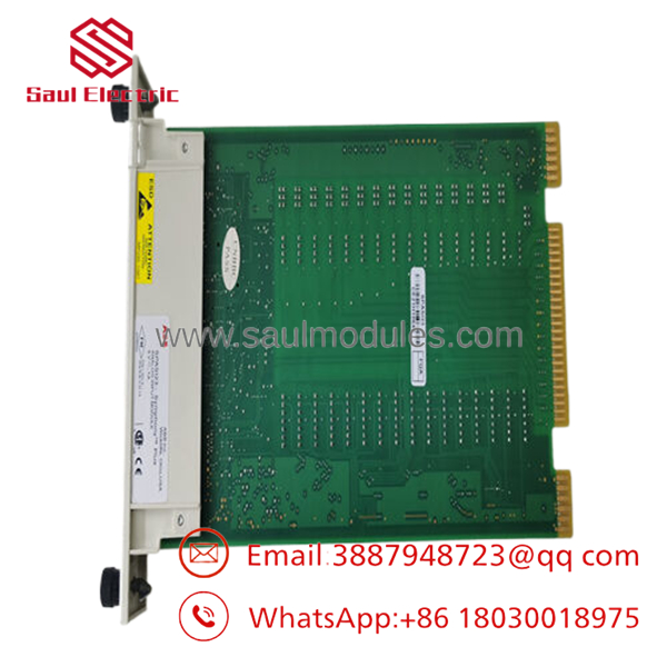
- SPASI23
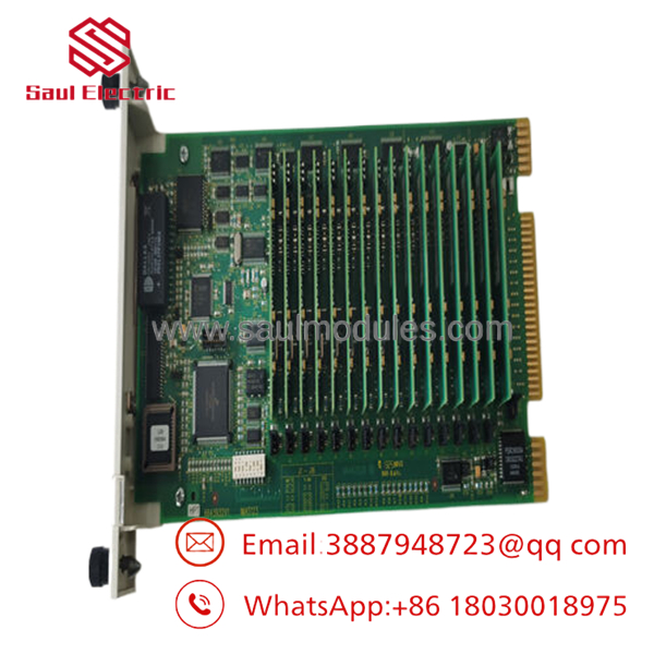
- SPASI23
Installation & Configuration Guide
Stage 1: Pre-Installation Preparation (Estimated Time: 10 minutes)
- ⚠️ Safety First: Notify plant operations of localized system downtime before servicing the rack module. Ensure the relevant loops are placed in a safe manual or tripped state. Verify that the rack power supplies are operating stably.
- Tools Required: Grounded anti-static (ESD) wrist strap, small flat-head terminal screwdriver, smartphone or camera for physical configuration tracking.
- Data Backup: Before extraction, verify that the master controller has an active, up-to-date backup of the system configuration. Note down the physical dip switch positions and jumper blocks located on the side of the module housing or the accompanying termination unit (TU).
Stage 2: Removing the Old Module (Estimated Time: 5 minutes)
- Attach your grounded ESD wrist strap to the designated grounding point on the module chassis or enclosure frame.
- Unlatch the faceplate plastic locking tabs positioned at the top and bottom of the SPASI23 module.
- Gently pull the module forward out of its slot guides in the Harmony Rack structure. Pull straight outward to avoid warping or damaging the backplane multi-pin connector.
- Slide the card completely out of the slot and position it inside an anti-static bag. Inspect the backplane slot for debris or dust accumulation.
Stage 3: Installing the New Module (Estimated Time: 10 minutes)
- Remove the new from its static shielding package while maintaining grounding protocols.
- Configuration Clone (Crucial): Examine the onboard dip switch blocks and jumper positions on the new board. You must modify these switches to mirror the old card’s configuration precisely. These switches govern channel pairing (single-ended vs. differential), input filter options, and cold-junction compensation variables.
- Align the circuit board edges with the top and bottom card guides inside the target rack slot.
- Smoothly slide the module inward until the rear pins mate securely with the backplane connectors. Push firmly on the faceplate edges until the top and bottom clips snap locked.
📋 Self-Checklist:
- [ ] Hardware dip switches match the legacy module configuration exactly.
- [ ] Module is fully seated into the Harmony backplane with clips engaged.
- [ ] Field termination cables are clear of the card edge slot paths.
Stage 4: Power-On & Testing (Estimated Time: 10 minutes)
- Slide the module home; the backplane power connects instantly upon insertion.
- Observe the front panel LED cluster status indicators. A successful boot is indicated by a stable green status light, while an active red LED indicates a localized self-test hardware fault or configuration error.
- Access the system engineering software station (e.g., Composer or S+ Engineering) to check the module diagnostic registers.
- Verify channel input readings against an external field simulator or a manual fluke measurement at the termination block to confirm proper digitization and calibration scaling.
- ⚠️ Troubleshooting Note: If the module status light flashes red or throws an I/O mismatch error at the controller console, pull the module and immediately check for a mismatched dip switch block or an unmapped channel definition inside your controller database configuration.
Frequently Asked Questions (FAQ)
Can this module be hot-swapped under live power conditions?
Yes. The Harmony Rack and Symphony Plus architectures allow for the hot-swapping of I/O modules like the under power without interrupting the operation of adjacent active modules. However, you must execute the swap with a grounded ESD wrist strap to avoid static discharging onto the backplane. Keep in mind that pulling the module will instantly drop all 16 process loops to their configured default/fail-safe values, so always place dependent control loops into manual override before extraction.
My application uses thermocouples. Does the provide cold-junction compensation (CJC)?
Yes, the supports cold-junction compensation for thermocouple installations, but the processing depends on your termination unit setup. The compensation reference resistor is physically located on the modular termination unit block (such as a NTDI01 or equivalent). Ensure that the hardware jumpers on the module match the specific termination board style used in your cabinet, or your temperature readings will drift significantly based on internal panel ambient temperatures.
Will pulling this analog input card delete or corrupt the logic on the master CPU controller?
No. The execution logic, tag blocks, and operational parameters are compiled and hosted on the main Harmony Rack controller (such as a SPBRC410 or MFC module), not on the individual I/O modules. The is strictly a functional data translation layer. Swapping it out resets the hardware channel interfaces but will not alter your core system control code.
How do I configure channels between differential and single-ended inputs on this module?
Channel configuration on the requires a two-step alignment. First, the physical hardware dip switches or layout jumpers on the module body must be set to group channels accordingly (allowing up to 16 single-ended signals or 8 noise-rejecting differential signals). Second, the software block configuration inside your engineering database must match this hardware choice exactly. A mismatch will yield erratic floating measurements on adjacent channels.
Why choose a “New Surplus” over ordering a current production version from the OEM factory?
Legacy Harmony Rack/Infi 90 components often carry extended lead times or premium factory lifecycle support pricing when ordered directly. Our New Surplus inventory consists of functional, unused components sourced from excess warehouse allocations and cancelled system installations. This allows us to supply authentic, factory-sealed hardware immediately, cutting down emergency repair windows from weeks to days while offering a comprehensive 12-month warranty match.


 Start Chat


