





Description
Core Product Summary
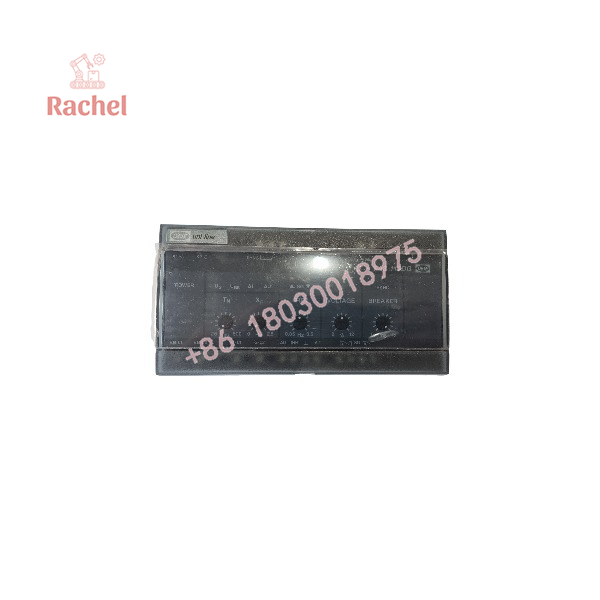
The DEIF FAS-113DG is a synchroniser in the Uni-line series from DEIF A/S of Skive, Denmark, applied for synchronisation of a generator to the busbar and closing of the generator circuit breaker when the voltage difference, slip frequency, and phase angle are within the preset limits. It is classified under ANSI code 25 and ordered under item number 2913010160 with variants for DC supply (variant 01) and AC supply (variant 02).
The FAS-113DG performs dynamic synchronisation, ensuring the slip frequency is always positive to prevent reverse power conditions, and compensates for the circuit breaker closing time by transmitting the closing signal a calculated number of degrees “before top”. Speed control uses a built-in P controller with relay outputs for frequency increase and decrease, settable via pulse length (TN, 25–500 ms), proportional band (XP, 0 to ±2.5 Hz), and a 0.05 Hz deadband. A synchronising signal is issued when the voltage difference is within ±2 to ±12 % of busbar voltage and the frequency difference within ±90 % of the set slip frequency. The unit provides analogue frequency and voltage outputs for common control with DEIF load sharing units LSU-112/113/114DG and LSU-122DG, input filters plus a df/dt (ROCOF) protection function against imprecise synchronising pulses, LED status indication, and self-monitoring with a status output. It mounts on 35 mm DIN rail or base and weighs approximately 0.75 kg.
Key Technical Specifications
| Parameter | Value |
|---|---|
| Product type | Synchroniser, Uni-line series (ANSI code 25) |
| Item number | 2913010160 (variant 01: DC supply; variant 02: AC supply) |
| Function | Generator-to-busbar synchronisation and circuit breaker closing |
| Synchronising principle | Dynamic synchronisation; positive slip frequency to prevent reverse power |
| Breaker closing time compensation | Yes; BREAKER potentiometer, 20–200 ms (200–400 ms with option E) |
| Breaker closing pulse length | 400 ms ±10 ms |
| Accuracy of breaker closing | ±3° el. at 0.05–0.25 Hz slip; ±5° el. at 0.25–0.5 Hz slip |
| Speed control | Built-in P controller, relay outputs for increase/decrease; TN 25–500 ms, XP 0 to ±2.5 Hz, deadband 0.05 Hz |
| Synchronising criteria | ΔU within ±2 to ±12 % of UBB; Δf within ±90 % of set slip frequency; generator frequency higher than busbar frequency |
| Slip frequency setting (fset) | 0.05 to 0.5 Hz |
| Measuring voltage (Un) | 57.7 / 63.5 / 100 / 110 / 127 / 200 / 220 / 230 / 240 / 380 / 400 / 415 / 440 / 450 / 480 / 660 / 690 V AC |
| Supply voltage (Un) | 57.7–690 V AC ±20 % (max. 3.5 VA); 24 / 48 / 110 / 220 V DC −25/+30 % (max. 2.5 W) |
| Overload | 1.2 × Un continuously; 2 × Un for 10 s |
| Frequency range | 40 to 70 Hz |
| Contact ratings | AC1/DC1: 250 V AC / 24 V DC, 8 A; AC15/DC13: 250 V AC / 24 V DC, 3 A |
| Analogue outputs | Δf: −10/0/+10 V DC ≈ −5/0/+5 Hz; ΔU: 0/5/10 V DC ≈ 80/100/120 % of Un (−10/0/+10 V ≈ 90/100/110 % with option F) |
| Status output | Optocoupler, max. 30 V DC, 5 mA; activated (closed) when unit is working correctly |
| Protection against false synchronisation | Input filters and df/dt (ROCOF) function; flashing Δf LED indicates active df/dt blocking |
| Self-monitoring | Supervises built-in microcontroller; POWER LED (green: OK; flashing 2–3 Hz: running incorrectly) |
| Indication | LEDs for generator voltage, busbar voltage, Δf, ΔU, SYNC, and speed increase/decrease |
| Galvanic separation | 3250 V, 50 Hz, 1 min between inputs and outputs |
| Operating temperature | −25 to +70 °C |
| Climate / EMC | HSE to DIN 40040; IEC/EN 61000-6-1/2/3/4 |
| Protection / materials | Case IP40, terminals IP20 (IEC 529/EN 60529); plastics self-extinguishing to UL94 (V1) |
| Wire size | Max. 4.0 mm² single-stranded / 2.5 mm² multi-stranded; AWG 12–16 |
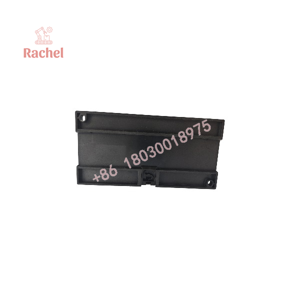
| Mounting | 35 mm DIN rail or base mounting |
| Weight | Approx. 0.750 kg |
| Approvals | Uni-line components approved by major classification societies; UL/cUL Listed on request |
Detailed Product Overview
The FAS-113DG automates the most delicate step in paralleling a generator: closing the breaker at the correct electrical moment. It continuously measures busbar and generator voltage, slip frequency, and phase angle. Speed matching is handled by the internal P controller, which drives the two relay outputs “SG” for speed increase and decrease with a pulse/pause pattern derived from the TN (minimum pulse length) and XP (proportional band) settings, leaving a 0.05 Hz deadband in which no control pulses are emitted. Because these settings are adjustable, the synchroniser serves both slowly reacting diesel engines and swiftly reacting gas turbines — the pulse behaviour is tuned to the governor’s response, not fixed at the factory.
Closing-time compensation is the feature that distinguishes a synchroniser from a simple match-check relay. The FAS-113DG measures the actual slip frequency, compares it with the breaker closing time set on the BREAKER potentiometer, and transmits the closing signal “x” degrees before top so that the contacts touch at the intended phase angle. The synchronising signal is issued only when three conditions are met: the voltage difference lies within ±2 to ±12 % of the busbar voltage, the frequency difference is within ±90 % of the FREQ setting, and the generator frequency is above the busbar frequency — the deliberately positive slip prevents reverse power after closing. The sync output contact is activated for 400 ms.
Signal integrity is treated explicitly. Harmonic distortion or noise on the voltage inputs can trick a synchroniser into issuing an imprecise pulse, so the FAS-113DG carries special filters on the AC inputs and, as a second line of defence, a df/dt (ROCOF) function that blocks the synchronising pulse if the filters cannot clean up the signal. An active df/dt block is shown by a flashing Δf LED. Where a governor’s response to engine firings produces jitter that cannot be tuned away, option C can disable the df/dt function — a decision that must be weighed against the stated worst case of a 180° out-of-phase synchronisation.
The analogue outputs integrate the FAS-113DG into multi-generator plants. The frequency difference output (terminal 36) and voltage difference output (terminal 33) support common control of DEIF load sharing units LSU-112/113/114DG and LSU-122DG, enabling simultaneous synchronisation of all generators of an island to the busbar. With option F, the voltage difference output is changed to −10/0/+10 V for DEIF Multi-line units such as PPU and GPC.
Six documented options tailor the unit to the plant: option A turns it into a frequency controller regulating the generator to 50/60 Hz ±0.05 Hz; option B adds the dead bus function, which controls frequency and voltage and closes the breaker onto an unenergised bus; option C deactivates df/dt protection; option D allows under- or oversynchronisation where fast paralleling outweighs reverse power risk; option E extends the breaker closing time range to 200–400 ms for slow breakers; option F re-scales the voltage difference output for Multi-line units. Options A and B are mutually exclusive, and the option letter is specified together with measuring voltage, supply voltage, and generator frequency at ordering.
Commissioning and diagnostics are well supported. A built-in phase-sequence check can verify wiring before energisation, the front LEDs indicate generator voltage, busbar voltage, Δf, ΔU, synchronising, and speed control activity, and the self-monitoring function watches the microcontroller and reports internal failure through a flashing POWER LED and the status output (terminals 17/18).
FAS-113DG
FAS-113DG
Engineering Selection Highlights
- Variant and order data: Item no. 2913010160 with variant 01 (DC supply, 24/48/110/220 V DC) or variant 02 (AC supply, 57.7–690 V AC); measuring voltage, generator frequency, and option letter must be specified at ordering.
- Prime mover matching: TN (25–500 ms) and XP (0 to ±2.5 Hz) settings adapt the control pulses to the governor — slow diesel engines and fast gas turbines are both covered by the same unit, correctly set.
- Breaker compatibility: Standard closing-time compensation covers 20–200 ms; breakers with closing times up to 400 ms require option E. The breaker time must be known at commissioning.
- Reverse power prevention: Dynamic synchronisation enforces positive slip (generator faster than busbar); where fast paralleling matters more, option D permits under/oversynchronisation.
- Multi-generator plants: Analogue Δf and ΔU outputs enable common control with LSU-112/113/114DG and LSU-122DG load sharing units; option F re-scales the ΔU output for DEIF Multi-line PPU/GPC units.
- Power quality at the installation: The input filters plus df/dt (ROCOF) function protect against noise- and harmonic-induced false synchronising pulses — relevant in plants with frequency converters on the busbar.
- Dead bus duty: Plants that must energise an unenergised busbar need option B (dead bus function); note that options A and B cannot be combined.
- Environment and enclosure: −25 to +70 °C operating range, IP40 case/IP20 terminals, 35 mm DIN rail or base mounting — suitable for switchboard internals; UL Listing is only available on request and is lost if the unit is re-customised outside DEIF production.
Dimensions, Mounting & Connection Notes
- Mounting: 35 mm DIN rail or base mounting, intended for installation inside switchboards and control panels.
- Weight: Approximately 0.750 kg.
- Protection: Case IP40, terminals IP20 (to IEC 529/EN 60529); operating temperature −25 to +70 °C.
- Terminals (selection): 1/3 supply voltage input; 8/9/10 breaker relay contact (on time 400 ms); 17/18 status output; 24/26 busbar voltage measurement L1/L2; 29/31 generator voltage measurement L1/L2; 34/35 inhibit input (INH); 33 voltage difference analogue output; 36 frequency difference analogue output; 35 common earth; 38/39 and 40/41 relay contacts “SG” for speed increase and decrease.
- Wiring: Use 60/75 °C copper conductors only; wire size AWG 12–16 or equivalent; max. 4.0 mm² single-stranded, 2.5 mm² multi-stranded. DC supply (UL variant) must come from a Class 2 power source.
- Relay note: The SG speed-control relay contacts should always be connected via external auxiliary relays when a DC pilot motor is used, with a transient suppressor across the external relay coils.
- Sealing: After mounting and adjustment, the transparent front cover may be sealed to prevent unwanted setting changes.
System Compatibility & Integration Requirements
| Item / Dependency | Verified Compatibility or Requirement | Practical Note |
|---|---|---|
| Primary function | Synchronisation of a generator to the busbar and closing of its circuit breaker | Closing signal issued only when ΔU, Δf, and phase angle criteria are met |
| Circuit breaker | Closing pulse 400 ms ±10 ms; closing time compensation 20–200 ms (200–400 ms with option E) | BREAKER potentiometer must be set to the actual breaker closing time |
| Governor interface | Two relay contacts “SG” for speed increase/decrease, AC1/DC1 250 V AC / 24 V DC, 8 A | For DC pilot motors, connect via external auxiliary relays with transient suppressors across the coils |
| Load sharing units | Analogue outputs for common control of LSU-112/113/114DG (Δf) and LSU-122DG (ΔU) | Enables simultaneous synchronisation of all generators of an island |
| Multi-line series (PPU/GPC) | ΔU output −10/0/+10 V ≈ 90/100/110 % of Un with option F | Standard output is 0/5/10 V ≈ 80/100/120 % of Un |
| Voltage measurement | Busbar and generator inputs; generator input activates above 60 % Un, busbar input above 80 % Un | An auxiliary contact on the generator breaker can reset the unit after synchronisation |
| Inhibit input | Potential-free N/O contact; when activated, no closing signal is transmitted | Usable for testing; different function with options A or B |
| Status output | Terminals 17/18, activated (closed) when unit works correctly; opens on internal failure | Can be wired to an alarm/monitoring circuit |
| Frequency modes | Standard synchroniser; option A: frequency controller 50/60 Hz ±0.05 Hz; option B: dead bus function | Options A and B are mutually exclusive |
| Mounting | 35 mm DIN rail or base mounting | Max. 4.0 mm² (single-stranded) / 2.5 mm² (multi-stranded) wiring |
| Approvals | Uni-line components approved by major classification societies; UL/cUL Listed only on request | Current approvals per DEIF; UL Listing lost if re-customised outside DEIF production |
FAQ
What is the DEIF FAS-113DG?
The FAS-113DG is a Uni-line series synchroniser (ANSI code 25) from DEIF that synchronises a generator to the busbar and closes the generator circuit breaker when voltage difference, slip frequency, and phase angle are within preset limits.
How does the FAS-113DG compensate for breaker closing time?
It measures the actual slip frequency, compares it with the breaker closing time set on the BREAKER potentiometer, and transmits the closing signal a calculated number of degrees before top so the breaker contacts close at the intended phase angle.
Which settings does the installer adjust?
TN (control pulse length, 25–500 ms), XP (proportional band, 0 to ±2.5 Hz), fset (slip frequency, 0.05–0.5 Hz), ΔUmax (acceptable voltage difference, ±2 to ±12 % of busbar voltage), and TBC (breaker closure time, 20–200 ms; 200–400 ms with option E).
How does the FAS-113DG avoid reverse power after closing?
It performs dynamic synchronisation, ensuring the generator frequency is always higher than the busbar frequency at the moment of closing, so the slip is always positive.
Which supply voltages are available?
AC supply 57.7 to 690 V AC ±20 % (max. 3.5 VA) or DC supply 24/48/110/220 V DC −25/+30 % (max. 2.5 W); variant 01 is the DC supply unit, variant 02 the AC supply unit.
Can the FAS-113DG synchronise onto a dead busbar?
Yes, with option B (dead bus function), it regulates generator frequency and voltage and transmits the closing signal when the busbar is unenergised; option B cannot be combined with option A.
How does it work together with load sharing units?
Its analogue frequency and voltage difference outputs support common control of DEIF LSU-112/113/114DG and LSU-122DG load sharing units, allowing simultaneous synchronisation of all generators of a plant.
What do the front LEDs indicate?
LEDs show generator voltage, busbar voltage, frequency difference (flashing Δf means the df/dt protection is blocking the sync pulse), voltage difference, synchronising relay activation (yellow SYNC), and speed increase/decrease activity; the green POWER LED is part of the self-monitoring function and flashes 2–3 Hz if the unit runs incorrectly.
Verification & Troubleshooting Notes
- No synchronising pulse is transmitted: Work through the three release conditions — voltage difference within ±2 to ±12 % of UBB, frequency difference within ±90 % of the FREQ setting, and generator faster than the busbar. Also check the Δf LED: if it flashes, the df/dt protection is blocking the pulse due to noise or instability on the inputs.
- Closing signal timing wrong after breaker work: The BREAKER potentiometer must match the actual circuit breaker closing time; verify it whenever the breaker is replaced or overhauled. Slow breakers up to 400 ms need option E.
- Speed hunting or slow paralleling: Review TN and XP settings against the governor’s reaction speed; jitter caused by a governor responding to engine firings is a documented trigger of the df/dt block.
- POWER LED flashing (2–3 Hz): The supply voltage is accepted but the unit is running incorrectly; the status output (terminals 17/18) opens and the unit should be replaced — do not attempt component-level repair.
- Dead bus unit runs the generator into overspeed: With option B, after breaker closing the voltage on terminals 29/31 or the supply on terminals 1/3 must be disconnected, otherwise the unit continues to raise speed; verify this interlock after any dead-bus closing.
- DC pilot motor applications: The SG relay contacts must operate through external auxiliary relays with transient suppressors; direct switching shortens contact life.
- UL Listed installations: UL Listing applies only to units supplied as UL Listed variants (24 V DC / 110 V AC supply), is lost if the product is re-customised outside DEIF production, and installation must follow the NEC (US) or CEC (Canada).
- Synchronising circuits connect to energised switchgear; follow the applicable electrical safety procedures, the DEIF installation instructions, and the switchboard’s safety documentation.

 Start Chat


