





Description
Core Product Summary (Brand / Model / Key Attributes)
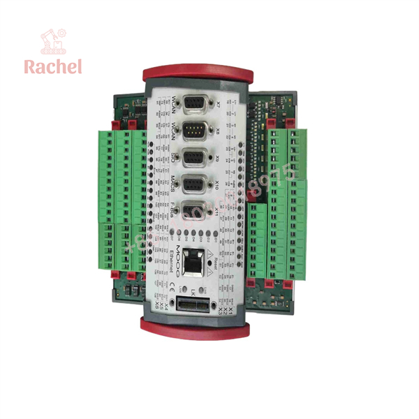
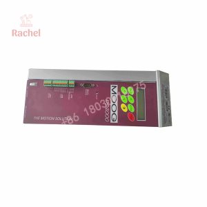
The Moog D136-001-007 is an MSC I motion controller in the Moog M3000 automation system family. It combines programmable logic control with motion-control functions, analog and digital signal handling, position-feedback interfaces, and industrial communication connectivity. A key model-specific feature is its PROFIBUS-DP slave interface, which distinguishes it from the D136-001-008 variant.
The controller provides eight configurable digital I/O points, eight 16-bit analog inputs, two analog outputs, two position-transducer interfaces, Ethernet, two CAN interfaces, and two EIA-232 serial ports. Its expansion bus supports additional compatible modules. These features make the exact ordering number important when matching the controller to an installed machine, particularly where PROFIBUS-DP communication is part of the control architecture.
Key Technical Specifications
| Parameter | Specification |
|---|---|
| Manufacturer | Moog |
| Model | D136-001-007 |
| Product type | MSC I Motion Controller |
| System family | Moog M3000 automation system |
| Digital I/O | 8 points, individually configurable as inputs or outputs |
| Analog inputs | 8 channels, 16-bit resolution |
| Analog outputs | 2 channels |
| Ethernet | 10BASE-T, 10 Mbit/s, 8-pin RJ45 |
| CAN | 2 independent interfaces |
| PROFIBUS-DP | Slave interface, up to 12 Mbit/s |
| Serial communication | 2 × EIA-232 |
| Position-transducer interfaces | 2 |
| Supply voltage | 24 V DC nominal, 18–36 V DC range |
| Mounting | DIN rail |
| Enclosure protection | IP20 |
Detailed Product Overview
The Moog D136-001-007 is a programmable MSC I motion controller intended for electric and hydraulic motion-control applications. It combines PLC functionality with configurable analog and digital I/O, position-feedback interfaces, and communication capabilities for integration into industrial machine-control systems.
Motion control and feedback
The MSC I platform is designed for closed-loop control of two axes, supporting position, speed, and force control. Its two position-transducer interfaces accommodate incremental encoder or SSI feedback configurations. These interfaces are relevant when coordinating actuator movement with measured position or other motion-related feedback.
During system selection, engineers should match the controller’s feedback configuration to the installed sensor type, signal format, and wiring arrangement.
Analog and digital I/O
The controller provides eight configurable 16-bit analog inputs and two 16-bit analog outputs. Input channels can be configured for voltage or current signals, including ±10 V, ±10 mA, and 4–20 mA. Output channels support ±10 V and configurable current-output modes.
Eight digital I/O points can be individually configured as inputs or outputs through the engineering software. The documented maximum current per digital output is 0.5 A.
These signal interfaces allow the controller to exchange process values, commands, and status signals with compatible field devices. The configured signal type and electrical limits must be considered when connecting the controller to existing instrumentation or actuator electronics.
PROFIBUS-DP and other communication interfaces
The defining interface distinction of the D136-001-007 is its PROFIBUS-DP slave interface, rated for communication speeds up to 12 Mbit/s. The controller also provides Ethernet, two CAN interfaces, and two EIA-232 serial ports.
For a machine connected to a PROFIBUS-DP master, the slave interface can be an important part of the controller selection. Integration still depends on the network configuration, device addressing, master configuration, and the applicable communication settings.
The controller also supports expansion through its side-mounted E-Bus connections, allowing compatible extension modules to be added within the documented system architecture.
Engineering software and configuration
Moog Axis Control Software (MACS) is the engineering environment used to program the MSC I and configure its hardware functions. The software is based on CODESYS and supports IEC 61131 programming.
For maintenance or replacement work, preserving the correct application program and hardware configuration is important. The controller’s ordering number alone does not establish that an existing machine project, communication configuration, or parameter set can be transferred without adjustment.
Dimensions, Mounting & Connection Notes
| Parameter | Specification |
|---|---|
| Dimensions (W × D × H) | 160 × 170 × 85.5 mm |
| Mounting | NS 35/7.5 DIN rail |
| Connection method | Plug-in terminal strips with screw or clamp connections |
| Operating temperature | +5 to +55 °C |
| Storage temperature | −25 to +70 °C |
| Relative humidity | 10–95%, non-condensing |
| Enclosure protection | IP20 |
| Supply voltage | 24 V DC nominal; 18–36 V DC range |
| Electronics current consumption | 0.5 A at idle; 2 A at full load |
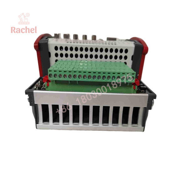
The controller uses plug-in terminal strips for electrical connections. Confirm that the required connection hardware is available and that the cabinet provides suitable space, environmental conditions, and wiring access.
Engineering Selection Highlights
- PROFIBUS-DP slave interface: Supports communication up to 12 Mbit/s; relevant when the controller must participate as a slave on an existing PROFIBUS-DP network.
- Two position-transducer interfaces: Support incremental encoder or SSI configurations; match the feedback format to the connected sensors.
- Eight analog inputs: Configurable for supported voltage and current signals; confirm that field instrumentation matches the selected input mode.
- Two analog outputs: Support voltage and current output configurations; check the command signal required by the connected equipment.
- Eight configurable digital I/O points: Each channel can be assigned as an input or output; confirm the required allocation and field-circuit current.
- DIN-rail installation: Uses an NS 35/7.5 mounting rail and an IP20 enclosure; plan for installation inside an appropriate electrical cabinet.
- MACS engineering environment: Supports application programming and hardware configuration; check the existing project and engineering setup before commissioning.
D136-001-007
D136-001-007
System Compatibility & Integration Requirements
| Item / Dependency | Verified Compatibility or Requirement | Practical Note |
|---|---|---|
| Controller family | Moog MSC I Motion Controller | Match the exact ordering number to the installed controller architecture. |
| PROFIBUS-DP | Slave interface, up to 12 Mbit/s | Confirm master configuration and network settings. |
| Ethernet | 10BASE-T, 10 Mbit/s, RJ45 | Check the network connection and communication configuration. |
| CAN | Two independent CAN interfaces | Confirm bus topology and transmission-rate settings. |
| Serial interfaces | Two EIA-232 ports | One supports MACS communication; the other is available for application use. |
| Analog I/O | Eight inputs and two outputs, 16-bit resolution | Match signal ranges and modes to the field devices. |
| Position feedback | Two interfaces supporting incremental encoder or SSI | Check sensor signaling and configuration. |
| Expansion bus | E-Bus supports up to seven additional modules | Confirm the selected extension modules and system configuration. |
| Engineering software | Moog Axis Control Software (MACS) | Check the application project and hardware configuration. |
FAQ
What is the Moog D136-001-007?
The Moog D136-001-007 is an MSC I programmable motion controller with integrated PLC functionality, analog and digital I/O, position-feedback interfaces, and a PROFIBUS-DP slave interface.
What is the main difference between D136-001-007 and D136-001-008?
The D136-001-007 includes a PROFIBUS-DP slave interface rated up to 12 Mbit/s. The D136-001-008 does not include that interface. This distinction is important when selecting a controller for a machine with an existing PROFIBUS-DP network.
Which communication interfaces are available?
The controller provides Ethernet, two independent CAN interfaces, two EIA-232 serial ports, and a PROFIBUS-DP slave interface.
How many analog and digital I/O points does it have?
It has eight 16-bit analog inputs, two 16-bit analog outputs, and eight digital I/O points that can be individually configured as inputs or outputs.
Which position sensors does it support?
The two sensor interfaces can be configured for incremental encoder or SSI operation, subject to the supported electrical and communication parameters.
Which engineering software does it use?
Moog Axis Control Software (MACS), based on CODESYS and supporting IEC 61131 programming, is used for controller programming and hardware configuration.
What power supply does it require?
The controller electronics operate from a nominal 24 V DC supply within a documented range of 18–36 V DC.
What should be checked before replacing an installed controller?
Confirm the complete model number, PROFIBUS-DP requirements, application program, I/O signal configuration, position-feedback wiring, power supply, and installed expansion modules before commissioning.
Verification & Troubleshooting Notes
- PROFIBUS-DP communication failure: Check the network wiring, master configuration, device addressing, and communication settings.
- Incorrect analog values: Confirm the configured signal mode and range against the connected field instrument.
- Position-feedback errors: Check encoder or SSI configuration, signal wiring, and sensor compatibility.
- Digital I/O faults: Verify channel configuration, field wiring, supply voltage, and output loading.
- Controller replacement issues: Confirm that the correct application program and hardware configuration are available before restoring machine operation.
Before changing connections or replacing control hardware, isolate hazardous energy sources and follow the machine’s approved electrical safety and commissioning procedures.

 Start Chat


