





Description
Key Technical Specifications
| Parameter | Specification / Value |
| Model Number | RDCU-12C |
| Product ID (Part Number) | 3AUA0000036521 |
| Application Platform | ABB ACS800 Inverter / MultiDrive Systems |
| Auxiliary Input Voltage | 24 V DC ±10% (via X34 terminal block) |
| Current Consumption | Maximum 1.0 A (excluding external options and outputs) |
| Analog Inputs | 3 channels (2x 0–20 mA, 1x 0–10 V); 12-bit resolution |
| Analog Outputs | 2 channels (0–20 mA); 10-bit resolution |
| Digital Inputs | 7 channels (24 V DC, galvanically isolated as a group) |
| Relay Outputs | 3 channels (form C); maximum 2 A at 24 V DC or 115/230 V AC |
| Reference Voltage Output | ±10 V DC ±0.5%; maximum load capacity 10 mA |
| Operating Temperature | 0 °C to +60 °C (32 °F to 140 °F) |
| Housing Material | Zinc-plated steel base with an ABS/PC cover plate |
| Physical Dimensions | 81.3 mm x 50.0 mm x 63.5 mm (3.20″ x 1.97″ x 2.50″) |
| Net Weight | 0.60 kg (1.32 lbs) |
Product Introduction
The ABB RDCU-12C (3AUA0000036521) is the primary physical drive control unit deployed across ABB ACS800 single and multidrive industrial frequency converters. This module provides the essential interface link between the raw inverter power electronics, the RMIO motor control board, and the wider plant-level DCS or PLC network.
Designed to manage real-time motor control loops, the RDCU-12C processes high-resolution analog and digital feedback directly at the drive level. It hosts three independent relay outputs, galvanically isolated digital input channels, and high-accuracy 12-bit analog input circuits. This modular configuration allows users to implement precise torque, speed, and position commands locally, protecting critical processing and mining machinery from raw electrical transients.
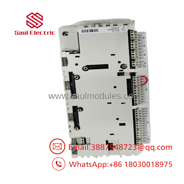
- RDCU-12C
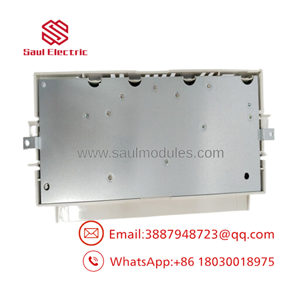
- RDCU-12C
Installation & Configuration Guide
Swapping out an RDCU-12C drive control unit requires a deliberate commissioning sequence, as a replacement board does not contain default system software.
Stage 1: Pre-Installation Preparation (Est. Time: 15 minutes)
- ⚠️ Safety First: Shut down the associated motor. Lock out and tag out (LOTO) the main AC incoming feeder to the ACS800 drive cabinet. Wait at least 5 minutes to let the internal DC bus capacitors discharge below 50 V DC. Verify the absence of voltage on the DC busbars with a certified digital multimeter before opening any protective covers.
- Tools Required: Grounded ESD wrist strap, small flat-head terminal screwdriver, cross-head screwdriver, and a laptop with DriveWindow or Automation Builder software.
- Data Backup: Connect your PC to the active RDCU unit via the fiber-optic link or the control panel interface. Save a complete parameter backup file (
.dwpformat) containing your drive’s specific tuning, motor identification run (ID Run) data, and custom I/O mapping.
Stage 2: Removing the Old Module (Est. Time: 5 minutes)
- Wear a grounded ESD wrist strap before touching any electronic assemblies inside the cabinet.
- Label and disconnect the terminal blocks (X20, X21, X22, X23, X34) from the board. Detach the X39 control panel ribbon cable.
- Gently pull any connected fiber-optic cables (if an RDCO module is attached) straight out of their optical jacks. Do not bend fiber cables beyond a 50 mm radius.
- Undo the mounting screws holding the metal base plate of the to the drive chassis, then lift the unit clear of the mounting DIN rail.
Stage 3: Installing the New Module (Est. Time: 10 minutes)
- Verify the replacement unit’s model number reads .
- If your old unit utilized an RDCO fiber-optic daughterboard, unscrew and carefully transfer it to the corresponding connector slot on the new .
- Snap the new base plate onto the 35 mm DIN rail inside the enclosure and secure the mounting screws.
- Plug in all labeled terminal blocks and reconnect the X39 ribbon cable, tightening terminal block screws to a torque range of 0.2 to 0.4 Nm (1.8 to 3.5 lbf·in).
Self-Checklist:
- [ ] Auxiliary 24 V DC wired correctly to terminal X34
- [ ] Fiber-optic RX and TX lines are not crossed (black to black, grey to grey)
- [ ] Shielded cables grounded at the entry clamp point
- [ ] Metal base plate has direct electrical contact with chassis ground
Stage 4: Power-On & Firmware Loading (Est. Time: 15 minutes)
- Apply control power (24 V DC auxiliary only) to the drive control unit. Do not power up the main three-phase line voltage yet.
- Observe LEDs: The green “Power” LED should illuminate. If the red “Fault” LED is lit immediately, this is expected as the spare board has no application software.
- Connect your laptop. You must flash the specific drive application software (e.g., Standard, System, or Master/Follower program) matching your drive’s specific power rating and framework.
- Download the saved drive parameter file backup.
- Restore main line power, run a low-speed dry test of the motor, and verify I/O handshakes with the plant PLC.
- ⚠️ Troubleshooting Note: If the drive reports an “Id Run” fault, the parameter restore may have locked out the previous motor model data. Re-run the reduced motor ID run to calibrate the new processor to your motor’s specific windings.
Frequently Asked Questions (FAQ)
Can I run the ACS800 drive immediately after physically installing the ?
No. Out of the box, a new is a blank hardware card that does not contain the drive application software. If you install it and power up the system, the drive will not run and will flag a configuration fault. Before the drive can operate, you must use ABB’s DriveWindow software to load the correct software package and write your saved parameter set back to the unit.
Can this control unit be hot-swapped while the drive is running?
Absolutely not. Removing any of the terminal blocks or pulling the board off the DIN rail while the unit is powered will interrupt critical speed feedback loops and cause an immediate drive trip. Additionally, hot-swapping can induce severe voltage spikes across the digital input terminals, causing permanent hardware failure on both the and the parent drive’s power modules.
Why does my replacement unit have a different country of origin listed than my original card?
ABB manufactures the (3AUA0000036521) across several global facilities, including Sweden, Finland, China, Estonia, and India. Despite differences in manufacturing location, all units are built to the identical electronic specification, physical dimensions, and electrical pinouts. They are 100% interchangeable without modification.
What is the purpose of the conformal coating on this card?
The “C” suffix in denotes a conformally coated circuit board. This thin protective polymeric film shields the delicate surface-mount components from airborne conductive dust, moisture, and corrosive atmospheric contaminants common in wastewater treatment facilities and chemical processing plants. It increases hardware longevity compared to non-coated variants.
How do I connect the CDP-312R control panel to this unit?
The control panel interface is managed through the X39 12-pin male header block located on the front cover of the . Use the standard flat ribbon cable supplied with your drive cabinet to connect the panel directly to this header. Ensure the alignment notch on the cable socket matches the guide channel on the header to avoid reverse-polarity damage.


 Start Chat


