





Description
Key Technical Specifications
| Parameter | Value |
| Model Designation | REX010 |
| ABB Ordering Code | HESG324426R0001 |
| Primary System Role | Active signal injection device for rotor 100% earth-fault protection (ANSI 64R) |
| Injection Voltage Method | Low-frequency square-wave/sub-harmonic voltage injection via coupling networks |
| Coupling Interface | Connects to the generator excitation field circuit via an external REX011 capacitor unit |
| Communication Interface | Dedicated fiber-optic interface linked to the REG670 generator protection relay |
| Isolation Rating | High-dielectric voltage isolation barrier protecting low-voltage processing circuitry |
| Power Supply Requirements | Derived from the master rack assembly or dedicated DC auxiliary bus inputs |
| Chassis Mechanical Profile | Standard rack-mounting or panel-surface mounting configurations |
| Operating Temperature | −10 to +55 °C (+14 to +131 °F) continuous operation |
| Storage Temperature | −40 to +70 °C (−40 to +158 °F) |
Product Introduction
The ABB REX010 (HESG324426R0001) is a highly specialized auxiliary rotor injection unit designed as a vital co-processor module for the Relion 670 series, specifically the REG670 Generator Protection System. It plays a critical role in large-scale utility power plants, co-generation facilities, and hydro pump stations by providing active, continuous 100% rotor earth-fault protection (ANSI 64R). By accurately detecting insulation degradation anywhere along the generator’s field winding or excitation circuit, the REX010 helps prevent localized thermal imbalances and catastrophic rotor-to-stator shorts.
Operating on an active sub-harmonic voltage injection principle, the REX010 generates a low-frequency AC voltage signal that is coupled into the rotor’s field winding via an external REX011 coupling capacitor unit. The module constantly evaluates the resulting leakage current profile. Because it uses an active injection method rather than relying on passive residual voltage tracking, the REX010 provides reliable insulation monitoring even when the generator is at a complete standstill or operating during a critical startup phase. It streams high-speed measurement data back to the REG670 master relay via a noise-immune fiber-optic link, isolating vulnerable low-voltage digital control loops from the high-energy field excitation circuit.
Comprehensive SOP Quality Control & Testing
To eliminate field initialization faults and maintain historical performance parameters, every surplus or stock REX010 module completes our strict quality validation routine prior to shipment.
1. Inbound Inspection & Traceability
- Part Number Identification: The hardware part number HESG324426R0001 and revision codes are systematically cross-referenced against original factory builds to confirm exact build parameters.
- Optical and Frame Audit: Technicians inspect the ST/LC fiber-optic transmitter/receiver port lenses for micro-scratches, check the condition of backplane multi-pin blocks, and ensure grounding tabs are fully intact.
- PCB Diagnostic Scan: Internal component layers are analyzed under high-intensity ultraviolet lights to verify there is zero evidence of component aging, flux discoloration, or track corrosion.
2. Live Functional Testing
- Test Setup: The module is mounted on a dedicated verification rack linked through an active REX011 simulator setup to an ABB REG670 Generator Protection IED.
- Power-On Status Verification: The module is energized, and the front diagnostic LEDs are logged to ensure the microprocessor completes its boot phase and enters a nominal operational state.
- Injection Signal Waveform Validation: Using a calibrated digital storage oscilloscope, technicians probe the output terminal lines to confirm the injection signal matches standard voltage and sub-harmonic frequency profiles.
- Fiber-Optic Data Verification: We measure the optical output power using an industrial light meter to confirm the transceiver operates efficiently within factory-rated milliwatt levels. Data packet integrity is tracked continuously through the REG670 interface.
- Report Logging: Oscilloscope wave logs, serial metrics, and light attenuation measurements are recorded into a serialized QC test document.
3. Electrical Parameter Testing
- High-Potential Dielectric Isolation: A 500 V DC isolation test is applied between the low-voltage electronics frame and the field coupling block terminals using a Fluke 1507 megohmmeter to ensure isolation barriers measure >10 MΩ.
- Chassis Ground Resistance: Ground track paths are audited from the main backplane ground lug to the outer door casing to verify values are under 0.1 Ω.
4. Firmware & Configuration Verification
- Revision Matching: The onboard microcode version is extracted to ensure compatibility with your plant’s active REG670 IED firmware baseline.
- Interface Alignment: Technicians verify the internal transceiver hardware settings match standard data mapping configurations.
5. Final QC & ESD Packaging
- Authorization Mark: A dated verification sticker is placed over the terminal housing seams.
- ESD Safe Bagging: The unit is wrapped in static-shielding material to neutralize environmental static threats.
- Heavy Impact Boxing: The packaged module is securely fitted inside tight, custom polyethylene foam blocks and nested inside a heavy-duty, double-wall corrugated box designed for safe global transit.
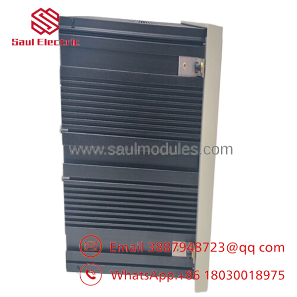
- HESG324426R0001
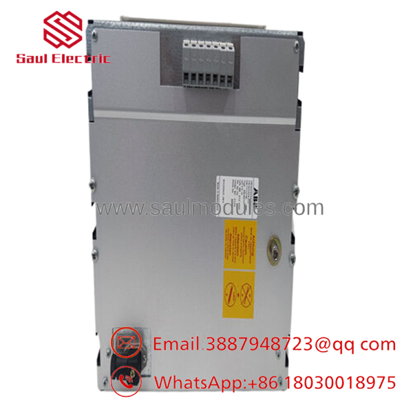
- HESG324426R0001
Technical Pitfall & Generator Protection Survival Guide
Replacing an active injection co-processor in a generator protection circuit requires strict attention to isolation boundaries and firmware alignment. Review these five common field replacement errors to protect your hardware and eliminate installation issues.
1. Swapping the Without Inspecting the External REX011 Coupling Capacitor
- ❗ The Risk: The active injection unit does not connect directly to the generator field windings; it relies on an external REX011 coupling capacitor unit to block the high-voltage DC excitation current from entering its low-voltage circuitry. If the failed because of an insulation breakdown or short circuit inside the REX011, plugging a new into the active loop will immediately expose the new module to the high-voltage DC field, damaging it instantly.
- 🛠| Mitigation: Always isolate the excitation circuit and use a high-voltage insulation tester to verify the health and capacitance of the coupling unit before connecting a replacement .
2. Fiber-Optic Cable RX/TX Swapping Confusion
- ❗ The Risk: The streams active current tracking and waveform feedback data to the master relay via a pair of fiber-optic cables (Transmit-TX and Receive-RX). Accidental cross-connection of these lines during an urgent system swap will cause a total communication loss, triggering a “Module Comm Fault” alarm on the DCS console and disabling your generator’s rotor earth-fault protection.
- 🛠| Mitigation: Label the TX and RX fiber lines clearly before disconnecting them from the old module. Clean the optical cable connectors with specialized fiber wipes before inserting them, and confirm that the RX port on the connects to the TX port on the .
3. Missing Mainframe Firmware Re-Synchronization
- ❗ The Risk: The master relay maintains a strict hardware inventory log. If the hardware revision suffix or firmware version embedded in the replacement does not align with the master relay’s project configuration, the will flag a hardware mismatch and refuse to process the injected signal parameters.
- 🛠| Mitigation: Use the PCM600 engineering software tool to check the existing firmware baseline of your system before installing the replacement. If a mismatch occurs, use the tool to flash the new module to match your system configuration baseline.
4. Modifying Injection Channel Wire Terminals Under Excitation Load
- ❗ The Risk: Working on the terminal wires between the and the coupling network while the generator is running and the excitation system is active exposes personnel to high voltages. It can also cause unexpected electrical noise spikes that may result in an immediate nuisance trip of the main generator breaker.
- 🛠| Mitigation: Never replace or wire the while the generator is operating or the excitation system is active. Ensure the generator is shut down, the field breaker is locked out, and all stored charge in the coupling capacitors has been fully discharged.
5. Neglecting Ground Loop Isolations at the Coupling Block Ground Frame
- ❗ The Risk: The active injection principle relies on a clean, low-impedance ground reference path to measure leakage currents accurately. If the grounding path for the or its coupling network is tied into an electrically noisy plant ground loop, the system will read false leakage currents, causing erratic insulation values and nuisance trips.
- 🛠| Mitigation: Ensure the chassis ground connects directly to a dedicated, low-noise instrumentation or protection ground bus using a short, heavy-gauge wire, bypassing dirty or high-current equipment ground lines.
Frequently Asked Questions (FAQ)
Why does the use active signal injection instead of passive voltage measurement?
Passive protection systems only monitor the residual DC voltage unbalance relative to ground, meaning they cannot detect insulation faults near the rotor’s electrical neutral point or when the generator is at a standstill. The avoids this blind spot by actively injecting a continuous, low-frequency sub-harmonic AC voltage. This active signal allows the system to monitor the insulation resistance of the entire rotor winding under all operating states, including standstill, startup, and full load conditions.
Can the module be used as a standalone rotor earth-fault relay?
No. The functions as an auxiliary signal generation and signal-processing co-processor, not a standalone relay. It lacks the internal output contacts and trip logic processors needed to clear breakers independently. It must be paired with an external ABB coupling capacitor unit and connected via a fiber-optic link to a relay, which processes the measurement data and executes any necessary trip commands.
What is the specific purpose of the fiber-optic interface on the ?
The fiber-optic link provides complete electrical isolation between the high-voltage generator excitation circuit and the low-voltage protection system. Because the connects directly to the rotor excitation loop via its coupling network, a catastrophic component failure could introduce high voltages into the signal lines. Using a fiber-optic link ensures that any electrical fault is isolated at the , preventing high-voltage surges from traveling down copper wires and damaging the main relay rack.
How often do the optical ports on the require cleaning or calibration?
The optical ports themselves are sealed and do not require periodic calibration. However, during an equipment changeout or if the fiber cables are disconnected, dust particles can settle on the lenses and cause signal attenuation. It is highly recommended to clean the fiber tips and port lenses with a specialized fiber-optic cleaning pen or lint-free wipes dampened with pure isopropyl alcohol before reconnecting the communication links.
Why should our plant purchase a new surplus instead of sourcing directly from factory production?
Sourcing a new surplus helps eliminate long manufacturing lead times that can span weeks or months for specialized grid protection components. Maintaining a verified surplus unit in your facility’s inventory ensures immediate availability during unexpected hardware failures, allowing maintenance teams to restore critical generator protection systems and minimize expensive downtime during unplanned outages.

 Start Chat


