





Description
Key Technical Specifications
| Parameter | Value / Specification |
| Part Number | SPBRC4000000 / SPBRC400 |
| Module Type | High-Performance Bridge Controller / Main Processor |
| Processor Type | 32-bit RISC Architecture |
| Memory Configuration | 16 MB Synchronous DRAM, 512 KB NVRAM, 4 MB Flash |
| Redundancy | Dedicated hardware redundancy link for hot-standby pairs |
| Communication Protocols | Cnet (Control Network), HN800 (Harmony Network), Modbus RTU / TCP |
| Instruction Execution Time | Less than 1.0 ms for typical control blocks |
| Maximum I/O Capacity | Up to 30,000 function blocks; supports hundreds of local/remote I/O |
| Power Input | 5 V DC, 24 V DC backplane derived |
| Current Consumption | 2.2 A at 5 V DC (nominal) |
Product Introduction
The ABB SPBRC4000000 is the flagship, high-performance multi-function controller for the Symphony Plus and Harmony Rack Distributed Control System (DCS) architectures. It acts as the central brain of the control node, executing complex process control strategies, batch algorithms, and advanced regulatory loops with high computational speed. The module simultaneously functions as a communication bridge, routing data seamlessly from field I/O devices across the HN800 or Cnet networks up to the human-machine interface (HMI) level.
Engineers specify the SPBRC4000000 for critical infrastructure and continuous process environments, such as large-scale power generation stations, petrochemical refineries, and municipal water treatment facilities. The controller is built for maximum uptime, supporting true seamless 1:1 hardware redundancy. If the primary processor experiences an internal fault, the backup hot-standby SPBRC4000000 instantly assumes control within milliseconds without disrupting active field outputs or communication lines.
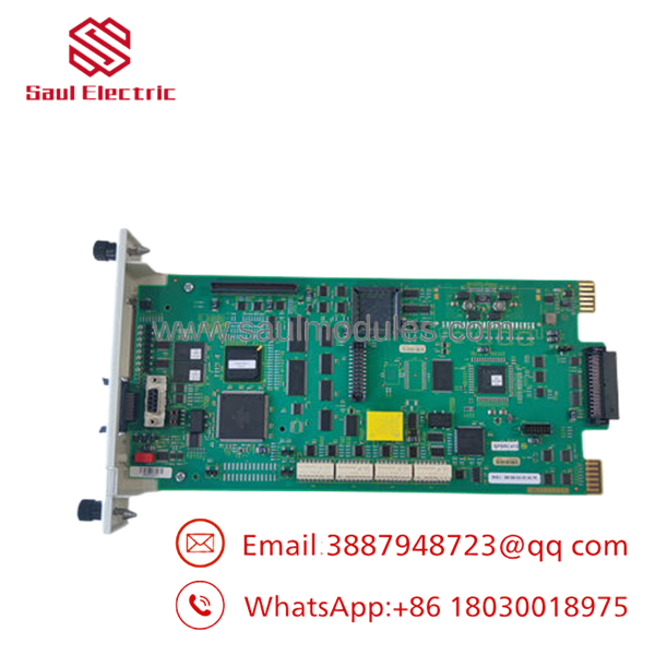
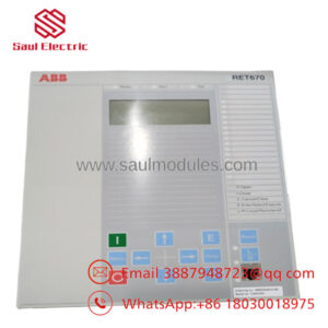
- SPBRC4000000
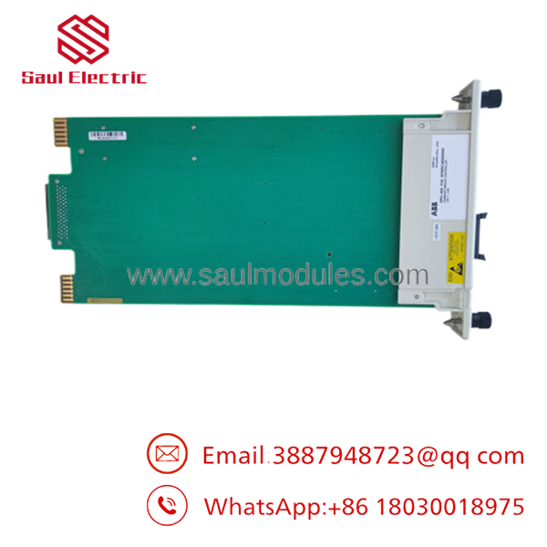
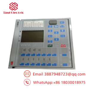
- SPBRC4000000
Installation & Configuration Guide
Stage 1: Pre-Installation Preparation (Estimated Time: 15 minutes)
- ⚠️ Safety First: Notify plant management and operations teams before swapping or inserting a main controller processor. Ensure that your secondary redundant processor is fully synchronized if performing a live online update, or confirm that the entire rack process can be safely isolated during a complete station outage.
- Tools Required: ESD grounding wrist strap, laptop with Composer or S+ Engineering software installed, compatible serial/ethernet configuration cable, smartphone for hardware switch documentation.
- Data Backup: Prior to removing an active controller, open your engineering workstation and execute a full configuration backup. Save the latest compiled
.cfgfile, compile the project, and export the current runtime tuning parameters to prevent losing setpoint modifications made by operators from the HMI.
Stage 2: Removing the Old Module (Estimated Time: 5 minutes)
- Attach your grounded ESD wrist strap to the rack frame grounding terminal.
- If replacing a failed unit in a redundant pair, verify that the target controller’s front panel status shows it is in Standby or Fault state, and that the remaining module has cleanly assumed the Primary control role.
- Loosen the upper and lower faceplate retaining screws on the module.
- Grip the module handles firmly, press the release clips, and slide the card straight out of the slot guides. Pulling at an angle can damage the high-density backplane connector pins. Place the module into a static-shielding bag immediately.
Stage 3: Installing the New Module (Estimated Time: 15 minutes)
- Keep your ESD strap connected while removing the new from its anti-static box.
- Configuration Clone (Crucial): Locate the dip switch banks (typically setting the Unit Address, Node Address, and Baud Rates) on the circuit board. You must set these switches to match the exact pattern of the old board. 3. Check the firmware version printed on the board label or manifest. If configuring a redundant pair,
- Slide the module into the designated slot guides. Push firmly until the backplane connector engages completely, and tighten the faceplate retaining screws.
📋 Self-Checklist:
- [ ] Hardware dip switches for Node/Unit address match the system layout.
- [ ] Firmware version matches the partner redundant controller precisely.
- [ ] Captive mounting screws are tightened down to ensure solid frame grounding.
Stage 4: Power-On & Testing (Estimated Time: 20 minutes)
- Upon fully seating the card into the energized backplane, the module will initiate its power-on self-test (POST) sequence.
- Monitor the front-panel alphanumeric or LED status display. A successful initialization should move past initialization states and show a normal operating state (such as stable green status lights).
- Connect your engineering laptop to the controller diagnostic port or access it via the control network.
- Open the S+ Engineering environment, establish communication, and perform a full configuration download of the backed-up control logic.
- If running a redundant pair, initiate the synchronization command via the software and verify that the new module transitions smoothly into a healthy Standby state.
- ⚠️ Troubleshooting Note: If the controller shows a red error code or an “Address Conflict” message on its display, immediately pull the module and re-verify your dip switch settings. Two controllers or nodes on the same network layer cannot share identical hardware address IDs.
Frequently Asked Questions (FAQ)
Can I replace a failed controller while the plant is running?
Yes, provided you have a healthy, functioning redundant pair configuration. If the sister controller is currently active as the “Primary” and running the process safely, you can un-slot the failed standby controller and slide the new into place. The new unit will boot up, check its hardware addresses, and allow you to synchronize the running logic directly from the active partner over the backplane redundancy link without bumping the process. If you do not have a redundant processor, pulling the card will instantly stop all execution logic, dropping your I/O loops to zero.
Will the new come pre-loaded with my control logic strategy?
No. Factory-new or surplus replacement units are completely blank apart from base operating system firmware. You must use ABB Composer or Symphony Plus Engineering software to connect to the newly installed module and download your site-specific compiled configuration (.cfg) file before the unit can process field signals or execute interlocks.
What is the purpose of the exact zeros in the part number suffix “000000”?
The trailing zeros in the full model number indicate standard hardware revisions without custom specialized factory modifications or regional add-on packages. It represents the standard, global-release high-performance BRC400 assembly that fits standard Symphony Plus Harmony rack configurations.
What happens if the firmware version on the replacement board is newer than my running primary controller?
This is a common issue with replacement hardware. If the new module’s firmware version does not match the active controller’s firmware, the redundant pair will fail to synchronize, and the primary unit will refuse to mirror data to the standby board. You will need to use your engineering toolchain to flash the firmware of the replacement backward or forward to match the exact revision of your existing installation before online redundancy will function.
Why does this controller command a premium price over standard distributed I/O boards?
The is not a basic input/output terminal card; it is a fully integrated, standalone 32-bit real-time computing engine designed to run tens of thousands of continuous logic blocks simultaneously. Its internal memory sub-systems, high-speed network routing chips, and low-latency failover circuits are highly specialized components engineered to operate continuously for decades without a reboot, qualifying its role as a master control element.

 Start Chat


