





Description
Key Technical Specifications
| Parameter | Value / Specification |
| Part Number | 1VCR007346 G0028 |
| Associated Controller | SUE3000 Central Unit / REF 542plus Base Unit |
| Housing Design | Generation 2 White Bezel / Faceplate |
| Display Component | Multi-line backlit LC display with contrast adjustment |
| Visual Indicators | Configurable LEDs for breaker position (open/close) and system alarms |
| Local Interface | Fixed control keys for open/close commands and manual transfer initiation |
| Connection Cable | Heavy-duty shielded serial connection to the central processor unit |
| Power Feed | Low-voltage DC derived directly from the REF 542plus base unit |
| Ingress Protection | IP54 when flush-mounted in panel door front |
| Operating Temperature | −5 to +55 °C |
Product Introduction
The ABB SUE3000 1VCR007346 G0028 is the front-panel Human Machine Interface (HMI) designed exclusively for the SUE3000 High Speed Transfer System and REF 542plus multifunctional control installations. This specific white-bezel unit acts as the primary physical access window for plant maintenance personnel and operators, providing real-time data on busbar voltages, line synchronization phase angles, and breaker statuses. It allows for immediate intervention, enabling manual initiation of high-speed bus transfers during targeted substation clearings or maintenance routines.
This HMI sub-assembly is selected to sustain localized operation of ABB’s dual-feeder and bus-coupler topologies across medium-voltage switchgear networks. The unit features built-in status LEDs mapped to a standardized mimic diagram, instantly revealing whether the main or standby incomers are carrying load. By insulating the display and control keypads from the high-voltage interior compartment via secure serial data coupling, it ensures safe panel-front operations in thermal power plant auxiliary networks and critical automated industrial complexes.
Installation & Configuration Guide
Stage 1: Pre-Installation Preparation (Estimated Time: 10 minutes)
- ⚠️ Safety First: Ensure that the primary SUE3000 Central Unit is isolated from control voltage before disconnecting the HMI panel. While the front display operates on low-voltage DC derived from the base controller, reaching inside the low-voltage door frame places you near live 110 V / 220 V DC control circuits, trip coils, and CT/PT terminal blocks.
- Tools Required: ESD grounding strap, small cross-head screwdriver, 5.5 mm nut driver or socket for panel-clamp lugs, smartphone.
- Data Backup: The 1VCR007346 G0028 unit is a display terminal and does not store the master protection logic, FUPLA configuration, or event logs (which reside inside the central unit flash memory). No parameter download is required, but you must note down any customized paper slide-in labels used for binary alarm indicators on the old faceplate.
Stage 2: Removing the Old Module (Estimated Time: 10 minutes)
- Fasten your ESD wrist strap and connect the clamp to a bare metal portion of the switchgear panel frame.
- Unplug the low-voltage serial data umbilical connection and grounding wire from the rear side of the active HMI unit.
- Use a 5.5 mm tool to back off the mounting clamps or nuts securing the HMI body against the rectangular cutout of the low-voltage compartment door.
- Support the front face of the HMI with one hand while removing the final clamps from the inside to prevent the unit from falling forward onto the floor.
- Push the unit gently outward through the panel cutout and slide it free.
Stage 3: Installing the New Module (Estimated Time: 10 minutes)
- Unbox the new 1VCR007346 G0028 unit, taking care not to scratch the glass or puncture the rubber sealing gasket running along the rear rim.
- Insert the unit from the front side of the door panel cutout, verifying that the display orientation is upright and centered.
- Fit the mounting brackets into the side grooves of the HMI housing from the inside of the door panel.
- Tighten the retaining nuts evenly until the rubber gasket compresses firmly against the sheet metal. Do not over-torque the nuts, as excessive force will crack the plastic bezel.
- Reconnect the serial data cable to the dedicated port, ensuring the locking clips click home. Attach the auxiliary ground wire braid to the grounding stud on the rear metal shielding plate.
📋 Self-Checklist:
- [ ] Rear sealing gasket is flush and compressed evenly to maintain IP54 rating.
- [ ] Earth grounding strap is reconnected and tightened at the back of the HMI.
- [ ] Umbilical communication cable is fully locked into position.
Stage 4: Power-On & Testing (Estimated Time: 15 minutes)
- Re-apply the control power circuit breaker for the SUE3000 / REF 542plus system.
- Watch the display boot sequence; the screen should clear, initialize internal graphics, and establish communication with the central unit within several seconds.
- Verify that the mimic display green and red LEDs match the current physical breaker states (Open / Closed) as reported by the plant SCADA.
- Access the display menu options using the arrow keys to confirm that contrast, language configurations, and unit firmware identifiers are legible.
- ⚠️ Troubleshooting Note: If the HMI powers up but flashes a “Communication Loss” or “No Link” error message continuously, check the serial data umbilical connection. The G0028 variant requires solid, shielded serial lines, and an improperly seated connector or pin bend will stall data mapping from the central processing relay.
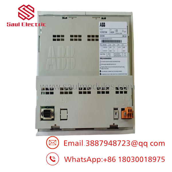
- SUE3000 1VCR007346 G0028
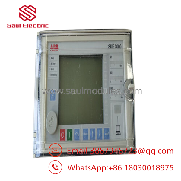
- 1VCR007346
Frequently Asked Questions (FAQ)
Can I hot-swap this HMI while the High Speed Transfer System is armed and active?
Yes, you can physically disconnect and replace the HMI without tripping the main breaker or disabling the automatic high-speed transfer functionality. The central unit handles the real-time processing, analog measurement evaluations, and fast-trip executions completely independently of the front display board. However, while the HMI is unplugged, you will lose all panel-front visualization, manual override controls, and localized alarm metrics. It is highly recommended to place the automatic transfer loop into “Block” mode temporarily on your overriding SCADA interface during the swap as a safety precaution.
What is the mechanical difference between the old black HMI version and this white “” revision?
The suffix indicates the modernized white housing assembly layout for the REF 542plus and platform lines. Internally, the microprocessor control interfaces and data link layers match the older black variants, but the newer white units feature improved UV-stabilized plastic materials to reduce yellowing and brittleness in hot environment enclosures, as well as upgraded internal display backlight longevity profiles.
Why is the exact model suffix “” critical when placing an order?
The and REF 542plus components span across numerous build generations and sub-variants (G0012, G0022, , etc.). The “G” variant determines specific port layouts on the rear casing, integrated language pack defaults, and power compatibility metrics with the central unit. Swapping an unvetted variant code can result in a mismatch of the connection socket geometry or an inability to boot up due to internal hardware communication protocol variances.
Does this unit require programming via FUPLA block architecture after physical mounting?
No. The 1VCR007346 acts entirely as a dependent terminal display. It extracts all functional mimic data arrays, text string values, and custom button assignments directly from the central processor unit configuration sheet upon startup. As long as your primary central unit retains its configuration parameters, this new panel will immediately self-configure as soon as the communication link is initialized.
What indicates a failure on the HMI board versus an actual bus transfer error?
If the HMI screen stays completely dark but the primary central unit in the cabinet shows healthy green status flags and active fiber optic network traffic, the problem is localized to the HMI backlight or its low-voltage power feed line. If the display works but reports data errors or solid red LED indicators, the issue is not an HMI hardware fault; it is an active protective lock-out or configuration error being reported by the primary transfer system itself.


 Start Chat


