





Description
Key Technical Specifications
| Parameter | Value |
| Part Number | 3HAC2380-1 |
| Module Type | Base Computer Board / Main Board |
| Controller Compatibility | ABB S4C+ (M2000, M2000A) |
| Input Voltage | 24 V DC (supplied via backplane) |
| Power Consumption | Approximately 15–20 W (nominal board draw) |
| Processor Architecture | Embedded RISC processing framework |
| Communication Interfaces | Ethernet (Service Port), Serial RS-232/485, Backplane Bus |
| Operating Temperature | +5 to +45°C (+41 to +113°F) |
| Storage Temperature | −25 to +55°C (−13 to +131°F) |
| Relative Humidity | 5% to 95% non-condensing |
| Weight | 1.15 kg (2.54 lbs) |
| Dimensions | Standard S4C+ computer rack slot width |
Product Introduction
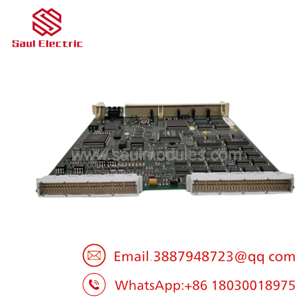
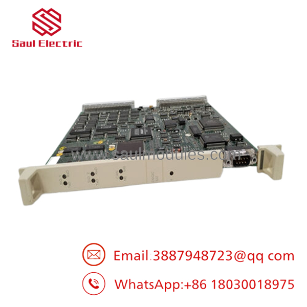
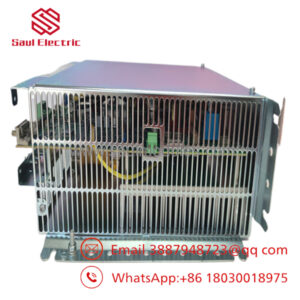
The ABB DSQC322 (3HAC2380-1) is the central base computer board utilized within the ABB S4C+ robot controller platform, predominantly governing M2000 and M2000A industrial manipulators. Operating as the hardware backbone of the S4C+ cabinet’s computing system, this board coordinates communication between the main CPU, drive modules, teach pendant, and peripheral I/O networks. It provides the low-level processing architecture required to execute precise kinematic trajectories and real-time motion control algorithms in demanding assembly, welding, and material handling environments.
Unlike newer modular processing units, the DSQC322 is selected strictly for direct maintenance and restoration of legacy S4C+ systems. It bridges high-speed system bus architecture with robust physical interfaces, ensuring deterministic control loops for attached robotic arms. Because this board directly impacts the initialization and uptime of the entire robot work cell, keeping an authentic, verified spare is standard practice for minimizing critical production stoppages.
Strategic Logic Frameworks
【Core Strategy 1: SOP Quality Transparency】
Because the DSQC322 is an obsolete part no longer rolling off ABB assembly lines, verified testing is non-negotiable. We mitigate your surplus-stock risks through a standardized, documented engineering inspection process:
- Inbound Inspection & Traceability:
- Source Verification: Every board is cross-referenced against factory lot codes and original OEM packaging logs.
- Anti-Counterfeit Check: Serial number registration data and physical holographic identifiers are inspected under magnification.
- Visual Audit: Boards are checked for surface scratches, traces of localized overheating, component yellowing, or post-factory solder rework.
- Live Functional Testing:
- Test Environment: Testing is conducted on a dedicated, operational S4C+ M2000 test cabinet rack linked to a dummy flex-pendant and simulator drive chassis.
- Power-On Self-Test (POST): We verify system boot order, monitor onboard diagnostic LEDs, and watch for immediate hardware fault flags.
- Communication Handshake: The board must execute an error-free ping across the Ethernet service port and establish a stable interface with the connected drive modules.
- Load Simulation: The unit undergoes a continuous 24-hour heat-run sequence inside the rack under simulated motion control routines while thermal imaging cameras check for component hot-spots.
- Reporting: A formalized test report is generated, logging physical serial inputs and diagnostic output data.
- Electrical Parameter Testing:
- Insulation Resistance: Rail-to-ground isolation checked via a Fluke 1587 FC insulation tester at 500 V, verifying resistance reads above 10 MΩ.
- Ground Continuity: Ground plane continuity checked across the backplane connector shield to ensure reliable noise mitigation.
- Firmware & Configuration Verification:
- Firmware Logging: Current boot ROM software version is indexed via standard service tools.
- Jumper Records: Visual and photographic confirmation logs the exact placement of onboard jumpers and hardware revision tags.
- Final QC & Packaging:
- Sign-off: Dual-stage verification signed by the testing engineer and QC manager.
- ESD Packaging: The board is sealed in an anti-static (ESD) shielding bag.
- Mechanical Protection: Wrapped in high-density foam padding and housed in a multi-wall corrugated box to withstand shipping impacts.
- Labeling: A physical “QC Passed” label containing the precise date of functional validation is affixed to the exterior layer.
Note: Comprehensive functional testing videos and specific test reports for your assigned board serial number are available upon request before dispatch.
【Core Strategy 2: Technical Pitfall & Survival Guide】
Replacing an S4C+ base board isn’t as simple as swapping a desktop PC card. Missing a small configuration detail can keep your line down for shifts. Keep these field realities in mind:
- Firmware Compatibility Trap:
- ❗ The Issue: The replacement DSQC322 may contain a boot ROM chip or base firmware mismatch relative to your current system software version loaded on the flash disk. This will trigger a critical boot loop or a continuous red system fault LED.
- Avoidance: Before pulling your defective board, use the service port to document your system software revision. Ensure your existing flash disk and boot parameters align with this physical hardware revision.
- Field Anecdote: “I worked an outage where a tech swapped a clean surplus board in, but the controller hung endlessly on startup. The replacement board had older boot ROM firmware that couldn’t read the newer image on the system flash card. We had to physically swap the old ROM chip over to get the line moving.”
- Onboard Jumper Configurations:
- ❗ The Issue: Default factory jumper layouts on a replacement card may not match your specific cabinet’s internal address or network termination profile.
- Avoidance: Take a clear, high-resolution smartphone photo of the failed board’s jumpers before extracting it from the chassis. Mirror those exact physical bridge settings on the replacement card.
- Field Anecdote: “This is a classic rookie oversight. A line was down for hours because an unmapped address jumper on a replacement card caused a system bus collision. Take that photo first—it takes ten seconds and avoids a ton of frustration.”
- Backplane Alignment and Pin Damage:
- ❗ The Issue: The multi-pin DIN connectors on the rear of the DSQC322 can easily bend if misaligned during insertion, permanently destroying the card or the backplane.
- Avoidance: Never force the board. Ensure the card sits squarely in its plastic guide rails before applying firm, even pressure on the card edges until it clicks home.
- Field Anecdote: “I watched a panicked maintenance tech slam a board into an S4C+ rack during a midnight breakdown. He bent three pins on the backplane, turning a simple 15-minute card swap into an absolute nightmare that required a complete backplane replacement.”
- Backup System Parameter Loss:
- ❗ The Issue: Swapping the base computer can disrupt local CMOS configuration memory or trigger file verification errors, causing a total loss of unbacked-up calibration and program data.
- Avoidance: Execute a complete system backup (
SYSFAILor regular system dump) to external media prior to decommissioning the old board.
- Static Electricity Damage (ESD):
- ❗ The Issue: CMOS components on the DSQC322 can easily degrade from static discharge that you can’t even feel, causing unpredictable intermediate faults weeks after installation.
- Avoidance: Use a grounded wrist strap attached to the cabinet frame. Never lay the bare board down on painted or ungrounded surfaces.
Installation & Configuration Guide
Estimated Time to Complete: 30–45 minutes
Target Audience: Maintenance Technicians / Automation Engineers
Stage 1: Pre-Installation Preparation
- ⚠️ Safety First: Bring the robot to a complete stop. Place the controller cabinet’s main disconnect switch into the OFF position. Apply lock-out/tag-out (LOTO) protocols to prevent accidental energization.
- Capacitor Discharge: Wait a minimum of 5 minutes for the drive amplifier DC bus capacitors to discharge down to safe voltage levels.
- Tool Check: Prepare a grounded ESD wrist strap, a medium flat-head screwdriver, a Phillips PH1 screwdriver, and a camera or smartphone.
- Data Validation: If the system is still responsive, capture a full backup of the system data, calibration variables, and program files (
*.mod,*.sys).
Stage 2: Removing the Old Module
- Attach your ESD wrist strap to a bare metal grounding point on the cabinet chassis.
- Open the computer unit protective cover.
- Take a reference photograph of all connected cables, bus wiring, and jumper placements on the old .
- Carefully disconnect any auxiliary cables (such as Ethernet service lines or serial connections) hooked into the front faceplate. Label each cable clearly.
- Loosen the upper and lower retaining screws on the board faceplate.
- Grip the board firmly by its ejector handles/tabs. Pull the card out straight and level along its guide rails to avoid torquing the rear pins.
- Place the old card directly into an antistatic bag. Inspect the interior backplane slot for debris or bent contact clips.
Stage 3: Installing the New Module
- Remove the replacement from its ESD bag while maintaining your grounded wrist strap connection.
- Configuration Clone: Compare the physical jumpers of the new board against the old module or the photo taken in Stage 2. Reconfigure the new jumpers to match the old setup exactly.
- Align the replacement board carefully within the upper and lower plastic guide tracks of the computer sub-rack.
- Slide the board smoothly toward the backplane. When you feel the rear connectors meet, apply firm, uniform force until the card seats flush against the rack frame.
- Tighten the faceplate retaining screws to lock the board into position. Do not over-torque.
- Reconnect all front-panel communication and interface cables according to your labels.
Stage 4: Power-On & Testing
- Conduct a final visual check to ensure no tools are left inside the computer rack.
- Remove LOTO locks and rotate the main cabinet disconnect switch to ON.
- LED Assessment: Immediately watch the front panel. The green power rails should light up. The system status LED should shift from a brief initializing amber/red state to a steady green operation indicator.
- Connect your PC to the service port using ABB RobotStudio Online.
- Verify that the system registers the correct hardware configuration and that no system bus communication faults are thrown.
- Calibration Check: Verify that the revolution counters and synchronization files match. If required, reload your system backup parameters.
- Conduct a low-speed, manual dry run using the teach pendant to confirm coordinate accuracy and axis response before releasing the unit to auto mode.
⚠️ Troubleshooting Note: If a solid red error LED persists on boot, power down immediately, isolate the system, extract the board, and verify that no rear interface pins were bent during installation.
Frequently Asked Questions (FAQ)
Can I hot-swap the board while the cabinet is powered up?
No, you cannot. The S4C+ backplane does not support hot-plugging for main computer assets. Attempting to pull or insert the card while 24 V rail power is applied can cause transient voltage spikes across the data lines. This will likely destroy the embedded processing chips on the board and can permanently corrupt firmware on adjacent modules. Always execute a complete power-down and LOTO sequence before extraction.
Since this model is obsolete, are these boards genuinely new or just repaired units?
The units we label as New Original / New Surplus are pristine, uninstalled pieces of inventory sourced from factory surplus buyouts, cleanroom spares, or canceled system integrations. They have never seen run hours in an operational production facility. Because they have sat in climate-controlled storage, they undergo our complete automated test sequence (SOP Quality Control) to ensure components like capacitors and flash arrays perform flawlessly. We explicitly label any field-salvaged or component-repaired units as “Refurbished” to maintain total transparency.
Will I lose my robot’s programming logic and calibration parameters when I replace this card?
The core system parameters and user programs on S4C+ controllers reside primarily on the flash disk or mass storage modules and the main CPU card rather than solely on the base board. However, changing the base infrastructure can alter system handshakes, sometimes prompting a cold boot or clearing the volatile SRAM cache that holds the current revolution counters. To protect your line from extended downtime, always assume data loss is possible: take a comprehensive system backup using the service port before pulling the physical card.
Why is your pricing significantly lower than ordering directly through OEM factory channels?
As an independent industrial automation supplier, we source surplus, overstock, and legacy system spares directly from plant upgrades and liquidations. We don’t carry the high corporate overhead or structured distribution markups that global OEMs build into legacy components. This allows us to pass real savings directly to maintenance teams while supplying authentic, tested hardware.
What is the exact difference between a and other S4C+ boards like the DSQC325 or DSQC321?
Each DSQC part number maps to a specific role within the S4C controller evolution. The serves specifically as a base computer mainboard for the S4C+ variant (M2000 series). Other numbers represent distinct iterations—such as the main CPU cards, safety boards, or I/O processors. They have completely different physical dimensions, pin configurations, and electrical specifications. They are not interchangeable. You must match the exact part number (3HAC2380-1) to ensure system compatibility.

 Start Chat


