





Description
Key Technical Specifications
| Parameter | Value |
|---|---|
| Model | YPC104B |
| ABB Part Number | YT204001-BT |
| Product Type | FSK Modem / Communication Board |
| Manufacturer | ABB |
| Primary Function | Industrial communication interface |
| Communication Technology | FSK (Frequency Shift Keying) Modem |
| Installation | Plug-in PCB |
| Compatible Systems | Legacy ABB industrial control platforms |
| Board Dimensions | Approximately 110 × 115 × 22 mm |
| Weight | Approximately 0.1 kg |
| Country of Origin | Sweden |
| Status | Discontinued / Legacy Spare |
Compatibility Note: ABB YPC104B (YT204001-BT) is primarily identified as an FSK modem communication board used in legacy ABB automation systems. Verify the exact hardware revision and system compatibility before replacement, as variants such as YT204001-BT/1 and YT204001-BT/2 may exist.
Product Introduction
ABB YPC104B (YT204001-BT) is an industrial FSK modem board designed to provide communication between ABB controllers, remote devices, and engineering workstations in legacy automation systems. It serves as a communication interface rather than a process controller, enabling reliable data transmission over supported industrial communication links.
This board is typically encountered during maintenance of older ABB DCS and control installations where remote diagnostics or controller communications remain in service. Before replacement, verify the controller type, communication architecture, board revision, and firmware compatibility to avoid unnecessary commissioning delays.
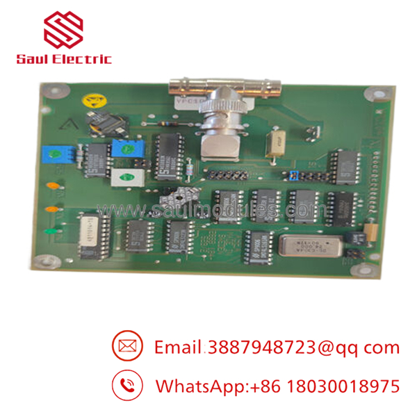
- YPC104B YT204001-BT
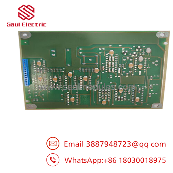
- YPC104B
Installation & Configuration Guide
Stage 1: Pre-Installation Preparation (Estimated Time: 10 Minutes)
⚠️ Safety First
- Notify plant operations before shutting down the communication system.
- Place the controller in a safe operating condition.
- Lock out and tag out cabinet power.
- Wait at least five minutes for power supplies to discharge.
Tools Required
- Grounded ESD wrist strap
- PH1 screwdriver
- Fluke 115 or equivalent multimeter
- Wire labels
- Smartphone for documentation
Data Backup
- Record controller configuration.
- Save communication parameters.
- Photograph every connector.
- Record modem address and communication settings.
- Document board location inside the rack.
Stage 2: Removing the Old Module (Estimated Time: 10 Minutes)
- Open the control cabinet.
- Label every communication cable.
- Disconnect connectors carefully without bending pins.
- Release retaining clips.
- Pull the board straight from the guide rails.
- Inspect the backplane connector for contamination or damaged contacts.
⚠️ Keep the original board until the replacement has completed communication testing.
Stage 3: Installing the New Module (Estimated Time: 10 Minutes)
- Wear an ESD wrist strap.
- Verify:
- Model: YPC104B
- Part Number:
- Configuration Clone (Critical)
- Match hardware revision.
- Restore communication settings.
- Verify any jumper or switch positions.
- Confirm cable orientation.
- Install the board firmly into the connector.
- Secure retaining hardware.
- Reconnect all communication cables.
Self-Checklist
- Correct part number
- Hardware revision verified
- Connectors fully seated
- Communication settings restored
- ESD procedures followed
Stage 4: Power-On & Testing (Estimated Time: 20 Minutes)
Pre-Power Inspection
- Verify control power.
- Inspect connector alignment.
- Confirm no loose hardware remains inside the cabinet.
Power-Up Procedure
- Energize the controller.
- Observe board status indicators.
- Verify communication initialization.
- Test communication with the engineering workstation.
- Confirm stable data exchange.
- Monitor communication diagnostics for errors.
⚠️ Troubleshooting Note
- No communication: Check FSK communication wiring, baud rate, and controller configuration.
- Board not detected: Verify hardware revision and connector seating.
- Intermittent communication: Inspect cable shielding, grounding, and signal quality before replacing the board.
Frequently Asked Questions (FAQ)
Q1. Can the be hot-swapped?
No.
This communication board should not be removed while the control system is energized. Live replacement can interrupt controller communications and may damage the backplane interface.
Q2. What is the primary function of the ?
The functions as an FSK modem communication board, providing reliable data transmission between ABB controllers and associated automation equipment in legacy control systems. It is intended for communication rather than direct process control.
Q3. Is the still manufactured?
The () is generally regarded as a legacy product. Most available units are sourced from new surplus inventory or specialist industrial spare-part suppliers rather than current ABB production.
Q4. What should I verify before ordering?
Confirm:
- ABB Part Number ()
- Board revision
- Controller model
- Communication protocol
- Connector style
- Existing firmware version
Do not rely solely on the board appearance, as different revisions may not be interchangeable.
Q5. Why is New Surplus inventory less expensive than factory pricing?
New Surplus modules are typically unused parts from cancelled projects, excess inventory, or discontinued product stock. Although unused, they should be inspected for serial number authenticity, physical condition, and communication functionality before installation.
Q6. What inspections should be completed before shipment?
A complete quality process should include:
- OEM label verification
- Serial number traceability
- Visual PCB inspection
- Power-on functional testing
- FSK communication verification
- Continuous burn-in test
- Insulation resistance testing where applicable
- ESD-safe packaging with QC documentation
Test photos and communication verification reports should be available upon request.
Q7. What is the most common field installation mistake?
Replacing the modem board without checking the communication network settings.
I’ve seen maintenance teams install a new only to discover the problem was an incorrect baud rate, damaged communication cable, or grounding issue rather than the board itself. Before replacing the hardware, verify the communication parameters, inspect the cabling, and confirm signal integrity. Those checks can eliminate most communication faults without replacing a working module.


 Start Chat


