





Description
Key Technical Specifications
| Parameter | Specification Value |
| Manufacturer | ABB / ASEA |
| Model Designation | YPI105C |
| Catalog / Part Number | YT204001-BK / BG 2668 0002-T |
| Voltage Configuration | 110 V DC nominal tracking threshold |
| Module Type | Digital Input Connection Sub-Assembly |
| I/O Isolation Type | Galvanic / Optocoupler status separation |
| Connection Style | Screw-terminal interface headers |
| Housing Dimensions | 14 cm x 10 cm x 4.5 cm |
| Net Weight | 0.125 kg |
| Country of Origin | Sweden / Switzerland |
| Operating Temperature | 0 to +55 °C |
Product Introduction & Supply Chain Strategy
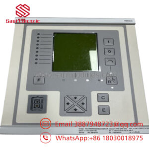
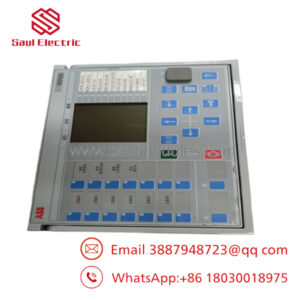
The ABB YPI105C YT204001-BK serves as a specialized 110 V digital input connection unit engineered for legacy industrial excitation systems, power converter sub-assemblies, and heavy-duty automation drives. This component routes and isolates binary control signals sent from high-voltage field switches, field-level interlocks, and circuit breakers back to the system processor framework. By introducing physical separation and filter paths, it protects microprocessors from high-voltage line spikes and ambient high-frequency electrical static.
Sourcing this specific legacy part as a New Surplus asset represents a critical capital insulation tactic for complex plants. Because this module interfaces field safety interlocks with core system controllers, relying on used or repaired hardware introduces high operational risks. Used connection units have often suffered insulation degradation and terminal wear caused by decades of chemical or thermal factory exposure. Opting for a verified New Surplus YPI105C maintains complete signal transmission performance, prevents unexpected line-monitoring dropouts, and avoids a forced, multi-million-dollar modernization project.
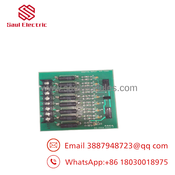
- YPI105C
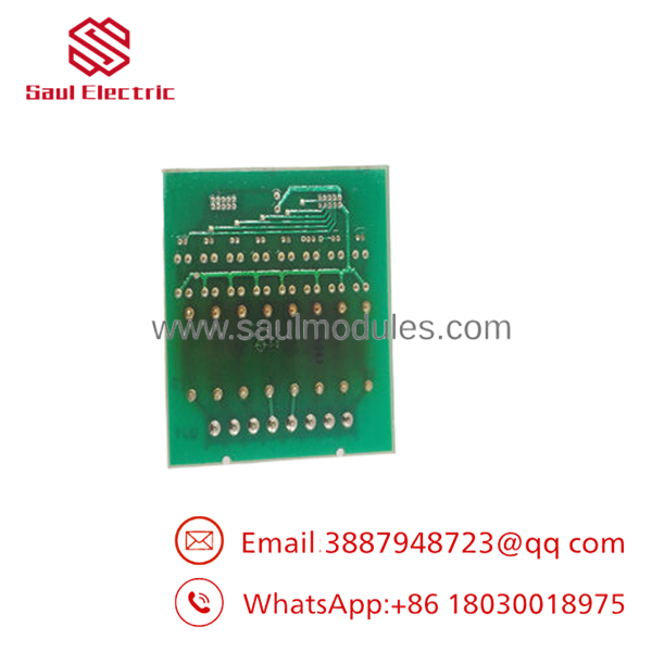
- YPI105C
Installation & Configuration Guide
Stage 1: Pre-Installation (Prep & Safety)
- Isolate the main control power circuit feeding the target expansion rack slot and apply full lock-out/tag-out (LOTO) protocols.
- Verify all external 110 V field input loops routed into the interface block are dead using a verified electrical multi-meter.
- Wear a grounded, static-free wrist strap to prevent static discharge from damaging internal board relays or optocouplers.
- Take reference photographs of the terminal connections and layout configuration parameters on the module being replaced.
Stage 2: Removal
- Loosen the terminal screws holding the input signal wires, noting the corresponding terminal numbering sequence.
- Detach any system ribbon data lines or backplane interface link pins on the module frame.
- Unfasten the retaining screws or release the mechanical assembly clips anchoring the unit housing onto the chassis layout.
- Carefully pull the module from its mount point and place it into an anti-static safety enclosure.
Stage 3: Installation (Clone & Seat)
- Verify the replacement YPI105C model matching code, voltage rating (110 V), and jumper layout match the parameters of the old hardware asset.
- Align the connection frame along the panel track or mounting pins and slide the module directly into place until it seats flat.
- Secure the structural screws firmly to anchor the housing against the continuous enclosure ground plane.
- Re-terminate each field wire into its corresponding screw socket, checking that no frayed copper strands cross adjacent terminals.
Stage 4: Power-On & Testing
- Re-engage the master 24 V auxiliary logic supply path while keeping the high-voltage 110 V input lines isolated.
- Confirm the module status indicators match system baselines and that zero immediate communication faults arise at the controller node.
- Remove the field line LOTO blocks, re-energize the 110 V input supply, and test individual field inputs to confirm accurate status mapping on the display panel.
- Close the cabinet door securely to restore the target environment seal profile.
Firmware/Software Versions & Upgrade Notes
The YT204001-BK functions as a hardware-configured terminal conditioning asset. It does not utilize downloadable application software packages, runtime driver boots, or active flash firmware variations.
However, because this model is matched directly to 110 V signal handling loops, ensure it is not interchanged with lower-voltage variants within the same physical series family. Mixing a 110 V card layout with components designed for alternate voltage thresholds can cause signal detection errors or immediate component failure within the tracking logic channel.
Frequently Asked Questions (FAQ)
What is the exact distinction between this New Surplus component and a standard factory item?
This unit is an authentic, original production component that has never been put into active service. It is a surplus item obtained from controlled distributor warehouses. It offers identical construction quality, component tolerances, and operational life parameters as a factory-direct part, but avoids the extensive factory lead times common with legacy components.
Does the require specific software configuration or parameter pairing?
No. The module is fully functional immediately upon completion of mechanical mounting and correct wiring termination. Since it acts as a passive signal conditioning connection unit, there are no internal software parameter structures to write, flash, or upload during a replacement event.
Can this board safely replace a model with an alternate suffix variant?
Not without confirmation. Suffix markers like YT204001-BK determine specific terminal layouts and input voltage levels (such as 110 V). Installing a mismatched card variant can result in input signal failure or over-voltage damage to the interface board. Always execute a direct part number match.
What are the operational issues associated with choosing a refurbished interface board?
Refurbished connection blocks often show micro-fractures inside terminal threads and degradation across the optical isolation channels. If an aging optocoupler slows down, signal detection lag times increase. This delay can prevent a critical system interlock from registering quickly enough to stop a downstream system fault.
What type of product warranty covers this legacy asset?
We protect this module with a comprehensive 1-year operational warranty. Because this unit is verified New Surplus stock with zero hours of field wear, we provide a full coverage window that guarantees stable voltage performance and zero component breakdown issues.

 Start Chat


