





Description
Key Technical Specifications
| Parameter | Specification Value |
| Manufacturer | ABB |
| Model Number | ZCU-12 |
| Part Number (Global ID) | 3AXD50000005751 |
| Compatible Drive Line | ACS880 Inverter Modules and Kits |
| Memory Port Interface | Accepts ZMU-02 / ZMU-03 memory units |
| Analog Inputs / Outputs | 2x AI (voltage/current selectable) / 2x AO (current mode) |
| Digital Inputs / Outputs | 6x DI (isolated) / 2x DIO (configurable direction) |
| Relay Outputs | 3x RO (form-C dry contacts, 250 V AC / 30 V DC, 2 A) |
| Safety Certification | Built-in Safe Torque Off (STO) to SIL 3 / PLe |
| Expansion Potential | 3x Option slots (Fieldbus, I/O extension, feedback encoders) |
| Internal Power Requirement | 24 V DC auxiliary input via terminal XPOW |
Product Introduction & Supply Chain Strategy
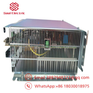
The ABB ZCU-12 3AXD50000005751 serves as the central intelligence and primary control hub for the ACS880 industrial variable speed drive platform. This processor assembly manages high-performance motor control configurations, computes active flux vector algorithms, and handles communication tracking across fieldbus adapters and local I/O terminal rows. Equipped with integrated hardware slots for the removable ZMU storage module and three independent option slots, the board offers seamless adaptation for complex process automation requirements.
From a supply chain reliability framework, storing a New Surplus ZCU-12 on-site provides vital financial security. When a master control unit fails due to ambient voltage surges or physical terminal stress, the entire production process stops. Choosing refurbished or pre-owned processing cards introduces high risks, as aged units frequently suffer from degraded micro-capacitors and trace failures that cause intermittent processing faults under heavy factory loads. A verified New Surplus ZCU-12 provides factory-fresh hardware timing profiles, maintains complete safety certification compliance, and allows immediate cold-swap recovery without OEM lead time dependencies.
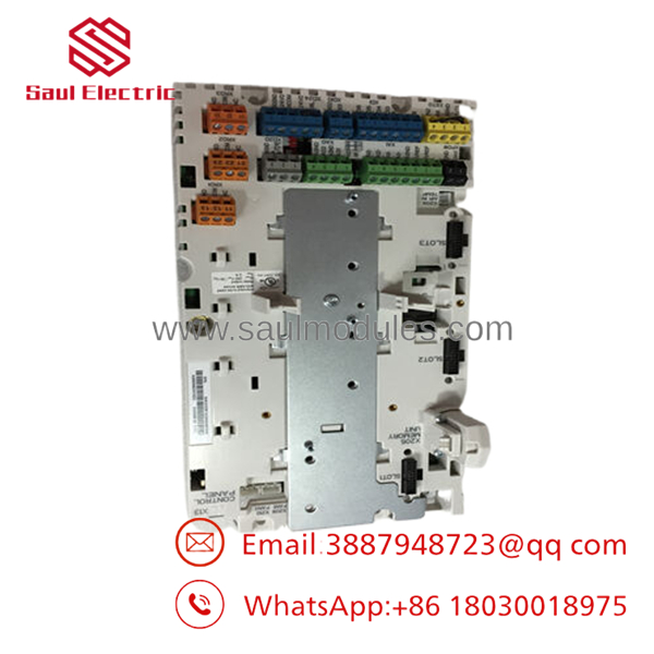
- ZCU-12
Installation & Configuration Guide
Stage 1: Pre-Installation (Prep & Safety)
- Isolate all primary incoming AC power lines feeding the ACS880 drive module and enforce strict lock-out/tag-out (LOTO) procedures.
- Wait a minimum of 5 to 15 minutes for internal DC bus capacitors to discharge down to safe levels. Verify zero potential across the positive and negative bus rails using a verified high-voltage meter.
- Attach a grounded anti-static wrist strap to your arm before opening the drive’s protective plastic face cover.
- Record high-resolution reference photographs of all I/O connection wires, communication interfaces, and option cards seated in slots 1, 2, and 3.
Stage 2: Removal
- Unplug the removable I/O terminal headers and communication plugs gently, avoiding stress on individual wire connections.
- Unfasten the retaining screws holding any option modules (e.g., FENA-11, FIO-11) and extract them straight out from their expansion slots.
- Release the plastic latch locking the ZMU memory module into port X205 and slide the memory stick outward; keep this safe as it contains your drive parameter configuration.
- Unscrew the primary mounting fasteners holding the ZCU-12 frame to the drive chassis assembly and lift the unit clear of the frame.
Stage 3: Installation (Clone & Seat)
- Position the replacement board over the internal metal alignment standoffs and screw the mounting fasteners down tightly to lock in a stable ground path.
- Slide your original ZMU memory unit into port X205 on the new board until the retaining clip snaps shut securely.
- Carefully line up and snap the option adapters back into their respective expansion slots, tightening their individual grounding and retention fasteners.
- Re-engage the removable terminal block headers into their matching colored sockets along the lower margin of the card.
Stage 4: Power-On & Testing
- Confirm the drive interior is free of loose tools or wires, then re-apply 24 V DC auxiliary control power (mains power should remain isolated).
- Observe the unit display panel; the system should automatically read the parameter configuration map from the original ZMU memory stick and boot into standard runtime mode.
- Audit the drive diagnostic log to ensure the dual-channel Safe Torque Off (STO) circuit balances correctly with zero safety fault overrides.
- Remove all LOTO blocks, re-engage the main three-phase supply lines, and execute a controlled motor spin test to confirm total operational integration.
Firmware/Software Versions & Upgrade Notes
The operational personality, firmware configuration, and parameter metrics of the are stored entirely on the removable ZMU memory module. When you swap a damaged board with a replacement unit while maintaining the original ZMU memory module, no specialized software firmware reloading or manual parameters calibration is required in the field.
However, if you are installing a new ZMU memory module along with the board, you must perform a firmware flash via the Drive Composer pro tool suite. Ensure the drive software application revision exactly matches the version of your adjacent parallel drive configurations to prevent synchronization errors or fieldbus node communication timeouts.
Frequently Asked Questions (FAQ)
Does this board come with a pre-installed ZMU memory module?
No. The is the hardware processor assembly board itself and does not include the ZMU memory stick by default. In standard field-replacement events, you simply pull the existing ZMU module from your old board and insert it directly into the replacement unit to retain your drive parameters and firmware settings.
Why should we choose a New Surplus over a cheaper refurbished processing board?
The control card handles complex math for real-time motor flux and safety loops. Refurbished units are often exposed to heavy thermal loads and vibration before being resold, which can cause micro-fractures in the solder layers or component drift. Sourcing a New Surplus unit ensures your critical safety functions and control loops operate with factory-new reliability.
Can this board be utilized across both low-power and high-power ACS880 drive systems?
Yes. The control unit is standard equipment across many frame sizes within the ACS880 industrial drive family. Its specific application behavior, power rating coordination, and current scaling limits are determined automatically by the configuration data stored on the plugged-in ZMU memory stick.
What is the purpose of the three option slots along the left side of the card?
These interfaces allow you to expand your drive’s capabilities by installing optional modules. Slot 1 is typically used for fieldbus communication adapters (like Profinet or Modbus), Slot 2 is designed for I/O expansion modules, and Slot 3 is configured to interface with speed feedback encoder boards.
What parameters are covered under the 1-year warranty package?
Our comprehensive 1-year warranty covers all processing component defects, I/O channel path failures, and terminal anomalies. If the control board experiences any signal failures or component defects during standard operation within this window, we will provide an immediate replacement module or issue a full refund.

 Start Chat


