





Description
Core Product Summary
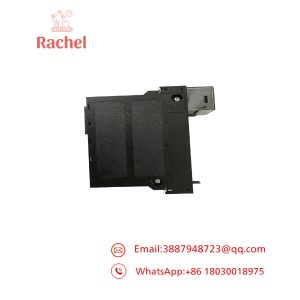
The Duplomatic DDC4-10-400/20 (order code format DDC4-10-40020) is a rack-mounted digital control unit from Duplomatic Automazione S.p.A. that manages the complete positioning and drive functions of Duplomatic SM* turrets, TRM-S turrets, and FL turrets on lathes. It is a fully digital, DSP-driven servo controller: it drives the turret’s brushless motor, executes the shortest-path search to the requested tool position, and coordinates the locking and unlocking electrovalves of the turret. Firmware versions covered by the installation documentation are 2.4, 2.6 and 2.8.
The unit is powered from a three-phase 400 Vac (+15%/−10%, 50/60 Hz ±2 Hz) supply for the power/driver section, drawing up to 10 A, plus a 24 Vdc ±10% auxiliary supply (35 W) for the internal driver logic and CNC I/O, and a separate 24 Vdc source for the electrovalve relays (2 A max, protected by a 3.15 A T fuse). Digital inputs are sink type at 24 Vdc (5 mA), signal outputs are MOS transistor N.O. sources rated 0.1 A, and electrovalve outputs are N.O. relay contacts rated 2 A. The I/O interface exchanges position code bits, parity, start, mode-select bits, LOCKED, INDEXD, and binary alarm bits (ALBIT1/2/4) with the CNC/PLC, and configuration inputs select tool-count, inertia level, and maintenance-speed operation without any mechanical changes. An RS232 serial line supports PC-based diagnostics and remote control. Operating range is 0–55 °C at 30–95% humidity; system parameters are factory-optimized and are not customer-modifiable.
Key Technical Specifications
| Parameter | Value |
|---|---|
| Product type | Rack-model digital turret control unit (DSP-based brushless servo controller) |
| Controlled devices | Duplomatic SM*, TRM-S and FL series lathe tool turrets (400 V versions) |
| Firmware versions (manual) | DSP FW 2.4 / 2.6 / 2.8 (I/O FW 5); diagnosis software DDC4SW*.EXE |
| Power section supply | 400 Vac +15% / −10%, 3-phase, 50/60 Hz ±2 Hz, 10 A max (DDC4-10-400) |
| Auxiliary supply | 24 Vdc ±10%, 35 W; external 1 A slow-blow fuse required |
| Electrovalve supply | Separate 24 Vdc source (CM2), approx. 2.0 A; protected by 3.15 A T fuse |
| Recommended transformer | 400 Vac ±10% primary, 1200 VA rated power, ≤5% voltage drop at 10 A rms during acceleration |
| External power-line fuses | 6 A T (suggested 4–6.3 A motor-start type) |
| Emergency stop | External power contactor on the 400 Vac line required |
| Digital inputs | Sink type, 24 Vdc ±10%, 5 mA @ 24 Vdc, opto-isolated |
| Digital signal outputs | MOS transistor, N.O. (source), 0.1 A max (PTC protection + fuse F7) |
| Electrovalve outputs | N.O. relay (source), 2 A max (fuse F6 protection) |
| CNC interface signals | Position code bits PBIT01–PBIT08(16), PARITY, PSTART, MODE01–03, SPDSEL; outputs LOCKED, INDEXD, ALBIT1/2/4 |
| Turret feedback inputs | LOCKSW, ULCKSW, ZEROSW, motor thermal detector switch (N.C.) |
| Configuration inputs | PTAB01/PTAB02 (tool count, e.g., 8/12, 6/12, 12/24, 8/16), PTAB03 (inertia level), SPDSEL (maintenance speed ≈20% of nominal) |
| Positioning functions | Automatic shortest path, fixed CW, fixed CCW, jog next tool, service, safety; automatic reference (zero) search on power-up |
| Lock/unlock recovery | Three automatic lock/unlock attempts before alarm 41 or 51 |
| Diagnostics | RS232 serial line for PC diagnostics/remote control; LED indication on inputs (green) and outputs (red) |
| Operating temperature | 0 to 55 °C |
| Humidity | 30–95% |
| Vibration | 4 G RMS short period; 0.5 G RMS continuous |
| Isolation | Entire unit opto-isolated from external circuits |
| Compliance | Tested to CEI EN 61800-2 and CEI EN 61800-3 + A11; external EMC filter required for stand-alone compliance |
Detailed Product Overview
The DDC4-10-400/20 belongs to Duplomatic’s DDC4 generation of turret controllers, which replaced the earlier DDC2 control rack. The key architectural change is that the unit is fully digital and DSP-driven: the position control, path selection and drive functions run in digital signal processing rather than analog circuitry, and EPROM-based parameter changes are eliminated — tool count and turret model are configured through the PC diagnosis software and through dedicated digital inputs instead of hardware swaps.
Functionally, the unit is the complete motion authority for the turret. On receipt of a position code, parity bit and start pulse (PSTART, minimum 30 ms) from the CNC, it unlocks the turret disc, rotates the brushless motor to the requested tool position using the selected strategy — shortest path, always-CW, or always-CCW — relocks the disc, and signals cycle completion through two handshake outputs: INDEXD (position reached, disc not yet locked) and LOCKED (disc locked, turret ready to cut). The separation of these two signals lets the machine tool start axis approach as soon as indexing completes, before final locking, which shortens tool-change time within the documented interface rules.
Configuration flexibility is a practical strength of the design. One unit can be set, purely by wiring two inputs, for two different tool counts (for example 8 or 12 positions), and the inertia range can likewise be switched between level 1 and level 2 with a dedicated input, matching the inertia tables that Duplomatic publishes for each turret size (e.g., SM-*-12 at 0.8/1.2 kg·m² up to TRMS-400 at 60/100 kg·m²). A maintenance-speed input immediately reduces turret speed to roughly 20% of nominal, for door-open or intervention situations, and is held until the end of the current positioning.
The unit also embeds protective behavior: an automatic lock/unlock retry (three attempts) before raising valve-related alarms, parity checking on the incoming position code, and continuous self-diagnosis with alarms reported as a group/sub-group binary code on the ALBIT outputs. The machine builder must, however, provide the surrounding safety and EMC infrastructure: a power contactor on the three-phase line for emergency stop, external fusing on all three supplies, and an external EMC filter for stand-alone compliance — Duplomatic explicitly states that the controller is not itself a safety device and that EMC and general-safety conformity of the installed machine rests with the machine builder.
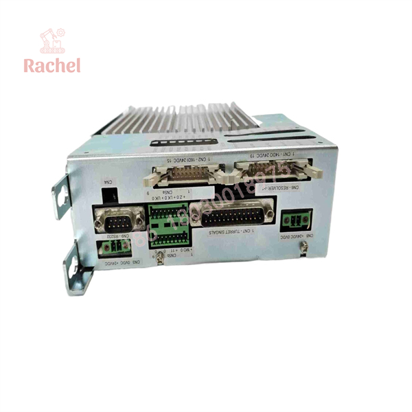
DDC4-10-400/20
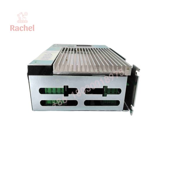
DDC4-10-400/20
Engineering Selection Highlights
- Exact-model mapping by hardware code — each unit carries a hardware code (0496322*xx series for SM/TRM-S/FL turrets) paired with a parameter table (0489100-4x) that matches a specific turret model and tool count; a replacement must match the turret it drives, not just the DDC4-10-400/20 base designation.
- Three-phase 400 Vac power section at 10 A max — the transformer must hold voltage drop within 5% at 10 A rms during acceleration; undersized supplies cause drive faults during the high-current indexing phase.
- Two separate 24 Vdc supplies required — one auxiliary source (35 W, 1 A slow fuse) for logic and CNC I/O, and an independent source for the electrovalve relays (~2 A, 3.15 A T fuse); sharing a single unprotected supply risks blowing fuses or disturbing the logic during valve switching.
- Opto-isolated I/O with defined signal levels — sink inputs at 5 mA and 0.1 A MOS outputs interface directly with 24 V PLC/CNC I/O without additional interposing hardware.
- Firmware-specific diagnosis software — the DDC4 generation requires the DDC4SW*.EXE diagnostic software; older DDC2-era tools are not compatible, so commissioning kits should include the current software version.
- Zero/reference cycle after every auxiliary power-up — the turret must execute a reference cycle and locks in position 1 before automatic operation; PLC logic must sequence this after each 24 V power-up.
- Operating envelope of 0–55 °C and 30–95% humidity — cabinet cooling must keep the rack within these limits, particularly since the 400 V driver section dissipates its own heat during indexing.
Dimensions, Mounting & Connection Notes
- The DDC4-10-400/20 is a “rack” model unit intended for fitting into the machine’s electrical cabinet; the installation manual includes overall-dimension drawings and cabinet fitting diagrams for the rack, servomotor cable, resolver/switch cable, driver supply, and digital I/O wiring.
- All connectors (inputs/outputs, feedback, motor) must be manipulated only with the unit disconnected from AC power; internal DC bus capacitors remain charged after power-off, so a waiting period applies before any connector work.
- The 400 Vac three-phase line requires external 6 A T fuses (4–6.3 A motor-start suggested) and a power contactor wired for the emergency-stop chain.
- The 24 Vdc auxiliary supply requires an external 1 A slow-blow fuse; the electrovalve 24 Vdc supply requires a 3.15 A T fuse.
- Servomotor and resolver/switch cables must be routed per the manual’s cabinet wiring diagrams to preserve EMC performance; shield continuity and separation from power wiring follow those drawings.
- Internal access is restricted: only personnel authorized by Duplomatic may work inside the unit; all parameter changes are made through the PC diagnosis software, not by opening the rack.
- Operating environment: 0–55 °C ambient, 30–95% relative humidity, vibration 0.5 G RMS continuous (4 G RMS for short periods).
System Compatibility & Integration Requirements
| Item / Dependency | Verified Compatibility or Requirement | Practical Note |
|---|---|---|
| Controlled turrets | Duplomatic SM*, TRM-S and FL series turrets, 400 V versions (per hardware code / parameter table pairing) | Tool counts and inertia limits are defined per turret size in the code tables |
| Power supply | 400 Vac +15%/−10%, 3-phase, 50/60 Hz ±2 Hz, 10 A max | External 6 A T (motor-start) fuses; external power contactor for emergency stop |
| Power transformer | 1200 VA rated, ≤5% voltage drop at 10 A rms | Check droop during acceleration against the unit’s voltage tolerance |
| Auxiliary supply | 24 Vdc ±10%, 35 W (CM1) | External slow 1 A fuse; fuse F7 = 1 A T in the unit |
| Electrovalve supply | Separate 24 Vdc source (CM2), ≈2.0 A | 3.15 A T fuse; drives EVLOCK/EVULCK relays |
| CNC input signals | PBIT01–PBIT08(16), PARITY, PSTART (≥30 ms), MODE01–03, SPDSEL | Sink-type inputs at 24 Vdc, 5 mA |
| CNC output signals | LOCKED, INDEXD, ALBIT1/2/4 | 0.1 A MOS N.O. source outputs |
| Turret feedback | LOCKSW, ULCKSW, ZEROSW, motor thermal switch (N.C.) | MDT-tool-system turrets may differ in lock/unlock switch wiring |
| Configuration | PTAB01/PTAB02 tool count; PTAB03 inertia level; SPDSEL maintenance speed | PTAB settings must be present at switch-on or alarm 77 is raised |
| Diagnostics | RS232 serial line to PC | Requires DDC4SW*.EXE diagnosis software |
| EMC | External filter required for stand-alone compliance | Compliance tested to CEI EN 61800-2 and 61800-3 + A11 with a turret |
FAQ
What is the Duplomatic DDC4-10-400/20?
It is a rack-model digital control unit from Duplomatic Automazione that drives and positions Duplomatic SM*, TRM-S and FL lathe tool turrets, handling motor control, path selection, locking/unlocking electrovalves, and the CNC interface in one unit.
What does the DDC4-10-400/20 do?
It executes complete tool-change cycles on demand from the CNC: it unlocks the turret disc, rotates the brushless motor to the requested position by the selected path strategy, relocks the disc, and reports cycle status through INDEXD and LOCKED signals, plus alarm bits.
What power supplies does it need?
A three-phase 400 Vac (+15%/−10%, 50/60 Hz) supply for the driver section (10 A max), a 24 Vdc ±10% auxiliary supply (35 W), and a separate 24 Vdc supply for the electrovalve relays (approximately 2 A).
Which turrets does it control?
Duplomatic SM*, TRM-S and FL series turrets in their 400 V versions, matched through the unit’s hardware code and parameter table to a specific turret model and tool count.
How is the number of tool positions configured?
Through two digital inputs (PTAB01/PTAB02) and the PC diagnosis software — two different tool counts (e.g., 8/12 or 6/12) can be selected with no mechanical modification; the setting must be present at switch-on or the unit raises alarm 77.
What diagnostic facilities does it provide?
An RS232 line for PC diagnostics and remote control (using the DDC4SW*.EXE software), green/red LEDs on every digital input and output for immediate wiring checks, and a binary alarm code output (ALBIT1/2/4 with position bits as the second digit).
What safety and EMC requirements apply?
The unit is not a safety device; the machine builder must provide an external power contactor for emergency stop, external fusing on all supplies, and an external EMC filter for stand-alone compliance. The controller itself was tested to CEI EN 61800-2 and CEI EN 61800-3 + A11 with a turret.
How does it behave after power-up?
A reference (zero) cycle must be executed after every power-up of the 24 Vdc auxiliary supply; at the end of the cycle the turret is locked in position 1 and ready for automatic operation.
Verification & Troubleshooting Notes
- Alarm codes: alarms appear as a group code on ALBIT1/2/4 with the second digit given on the position outputs; the manual’s diagnostic section lists extended alarm descriptions. When any ALBIT output is high, the machine should be stopped and the three-phase contactor opened; alarms can be acknowledged by setting the emergency/reset mode (MODE 000) for more than 30 ms and then switching to another mode.
- Turret will not start: check that PTAB01/PTAB02 (tool count) are set at switch-on — alarm 77 indicates missing configuration inputs.
- Intermittent alarm 7/73: in automatic mode, any change in position bits or parity not followed by a PSTART pulse within about 5 seconds raises this alarm — check for electrical noise or unstable PLC outputs on the position code lines, and avoid changing the position code immediately after LOCKED goes high.
- Repeated valve operation during tool change: the unit retries lock/unlock three times before raising alarm 41 or 51; recurring retries indicate a hydraulic pressure or valve problem that must be corrected before a permanent failure occurs.
- INDEXD signal behavior: INDEXD stays low during emergency mode and when the three-phase supply is off, so the PLC should use INDEXD only in-cycle and monitor LOCKED continuously when idle; a LOCKED drop outside cycle must stop the machine immediately.
- LED diagnosis: every input (green LED) and output (red LED) on the unit’s side provides a direct wiring check before any process diagnosis; use these first when commissioning or after wiring changes.
- Electrical safety: never manipulate connectors with AC power applied, and observe that internal capacitors remain charged after power-off; internal repairs and parameter modifications are reserved for Duplomatic-authorized personnel only.

 Start Chat


