





Description
Product Introduction & Engineering Value
When you run out of backplane slots in a legacy Series 90-70 rack, adding remote drops without introducing latency is a constant headache. The GE Fanuc IC697BEM713 Bus Transmitter Module solves this rack-space bottleneck by extending the high-speed CPU parallel bus across up to seven expansion racks via matching Bus Receiver Modules (IC697BEM711).
It occupies a single slot in the main CPU rack and hosts two primary ports: a dedicated high-speed parallel programmer interface and a bottom expansion port. Because configuration is handled directly inside Logicmaster 90 or VersaPro software, setup requires zero hardware jumpers or legacy DIP switches.
Technical Specifications
- Module Type: Bus Transmitter Module (BTM)
- Backplane Current Draw: 1.4 Amps @ +5V DC
- Maximum Cable Length: 50 feet (15 meters) total system length
- Effective Transmission Rate: 500 Kbytes/second
- Expansion Capacity: Up to 7 expansion baseplates (daisy-chained via Bus Receiver Modules)
- Interface Ports: Top: Parallel Programmer Interface; Bottom: Expansion Bus Port
- Communication Isolation: Non-isolated differential signaling
- Program Loading Speed: 16 Kbyte program transfer in 20 to 30 seconds
- Status Indicators: 3 Front Panel LEDs (MODULE OK, Programmer Port Enabled, Expansion Port Enabled)
- Rack Slot Compatibility: Single-slot width; must install to the right of any interrupt-generating modules (cannot occupy Slot 1).
Field Application & The “Trench” Experience
During an emergency midnight call at a municipal wastewater treatment facility, the plant’s main aeration control rack threw a remote drop loss fault. The legacy BTM module on the main Series 90-70 rack had suffered a damaged driver IC on the differential expansion port due to a ground loop over a 40-foot drop. The entire secondary blower rack went dark, threatening dissolved oxygen levels in the main basins.
Swapping in a replacement IC697BEM713 restored the high-speed 500 KB/s parallel link to all six expansion chassis in under twenty minutes without re-flashing PLC memory or toggling tiny switches.
Target Installation Scenarios:
- Polymer Extrusion Lines: Cascading multiple I/O racks across long multi-zone heater panels where local backplane access is constrained.
- Thermal Power Plant Auxiliary Control: Driving secondary turbine monitoring racks that require fast parallel data throughput to the central CPX processor.
- Retrofit Substation Control: Integrating legacy high-density discrete I/O chassis without splitting controller logic across separate CPUs.
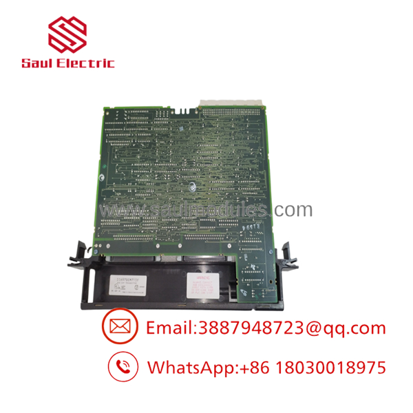
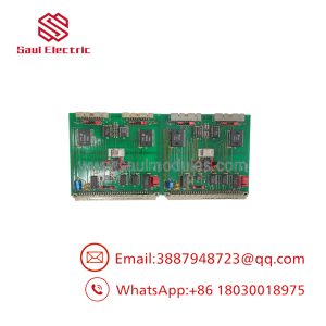
- IC697BEM713
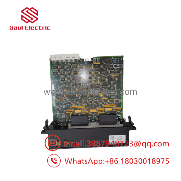
- IC697BEM713
Transparency SOP: QA & Testing
Every IC697BEM713 unit entering our surplus warehouse undergoes strict functional validation on an active VME-based Series 90-70 rack setup:
- Visual & Mechanical Inspection: Card guides, backplane pin blocks, and front port pin headers are inspected under magnification for bent pins or corrosion.
- Power-On Self Test: Module is mounted into slot 3 of a live IC697 rack to verify the +5V rail power draw stays within the 1.4A nominal limit.
- Loop & Drop Stress Testing: Connected via 50-foot shielded cable to a bank of IC697BEM711 receiver racks loaded with active discrete and analog modules.
- Data Integrity Pass: Logicmaster/VersaPro software runs continuous 100% loop transfers over the parallel programmer port to ensure zero dropped packets.
The Veteran’s Tech Trap Guide
⚠️ SLOT LOCATION RESTRICTION: Never seat the IC697BEM713 into Slot 1 of the CPU baseplate. Slot 1 is reserved exclusively for the main System CPU. Furthermore, place this card to the right side of any interrupt-source modules in the rack to avoid blocking backplane interrupt signals.
⚠️ CABLE DISTANCE HARD LIMIT: The 50-foot (15m) maximum distance applies to the entire total length of the expansion bus daisy chain, not per cable segment. Exceeding 50 feet leads to intermittent expansion port communication dropouts.
PRO TIP: If the MODULE OK LED remains dark after powering up, verify that all empty rack slots between the CPU and the BTM contain blank slot jumper cards (IC697ACC722). Missing jumpers break the backplane interrupt chain and prevent the CPU from clearing the module’s diagnostic boot check.
Dynamic FAQ
Q: Does the require firmware flashing or DIP switch setup prior to installation? A: No. The card contains no manual hardware switches. Configuration is completely software-driven through the CPU hardware configuration table in your programming software.
Q: Can I hot-swap this module while the Series 90-70 rack is energized? A: Absolutely not. Power down the main CPU baseplate before inserting or removing the module to avoid backplane bus faults or hardware damage.
Q: What is the warranty and condition on your stock? A: We supply both New Surplus (original factory box/un-commissioned) and fully reconditioned units. Every unit comes backed by our comprehensive 2-year full replacement warranty.
Q: Why is the bottom expansion port LED flashing instead of solid green? A: A flashing Expansion Port LED indicates active communications between the BTM and connected downstream Bus Receiver Modules (BRMs). If it turns solid OFF, the module has lost connection to the expansion racks.
Q: Can I connect third-party RS-232 or RS-485 serial cables to the top port? A: No. The top connector is a proprietary parallel programmer interface designed specifically for high-speed transfer with compatible programming units, not standard serial comms.

 Start Chat


