





Description
Product Introduction & Engineering Value
The GE IS2020DRLYH1AA provides relay-output interfacing between compatible Mark VI control electronics and external field circuits. Its 12 Form-C dry-contact relays allow the control system to switch external circuits without the terminal board itself serving as the field power source.
This is a wall-mounted DRLY assembly, not a standard DIN-rail terminal board, and it is intended for simplex operation. The H1A version also uses higher-power relay contacts than the H1B variant, making exact variant identification important during replacement.
Technical Specifications
| Parameter | Specification |
|---|---|
| Manufacturer | General Electric |
| Part Number | IS2020DRLYH1AA |
| Series | Mark VI Speedtronic |
| Functional Acronym | DRLY |
| Board Type | Relay Output Terminal Board |
| Redundancy | Simplex |
| Relay Quantity | 12 |
| Relay Contact Type | Form-C dry contact |
| Mounting | Wall-mounted |
| Processor Interface | 37-pin cable connection |
| Temperature Range | 0 to 65°C (32 to 149°F) |
| Compatible Processor Boards | VCRC/VCCC or compatible Mark VI processor architecture |
The available Mark VI documentation identifies the IS2020DRLYH1AA as a wall-mounted simplex relay-output assembly with 12 relay outputs and a 37-pin cable connection to the associated processor board.
Important: One third-party source incorrectly describes this exact part as a Mark IV board and provides specifications that conflict with the Mark VI technical references. For procurement purposes, the Mark VI identification and the GEH-6421C documentation cited by the technical reference are the safer basis.
Field Application & the “Trench” Experience
A relay-output board can fail in a way that looks like a field-device problem.
Consider a Mark VI turbine cabinet where one auxiliary pump refuses to start from the control sequence. The technician verifies that the control logic is issuing the command, then traces the signal toward the IS2020DRLYH1AA. The corresponding relay contact is checked, followed by the field wiring, contactor coil, and terminal connections.
The board is replaced only after the field circuit has been ruled out. Following installation, the technician verifies each affected relay output under controlled conditions before returning the equipment to automatic operation.
The critical point: a relay board should be tested at the contact level, not simply checked for power.
Niche application scenarios
- Mark VI turbine auxiliary-equipment control: switching discrete commands to contactors, solenoids, alarms, and other field devices.
- Turbine permissive and sequence outputs: providing relay contacts for control actions in simplex Mark VI installations.
- Legacy Mark VI maintenance: replacing a failed DRLY assembly without redesigning the existing field interface.
Transparency SOP: QA & Testing
For IS2020DRLYH1AA stock, use a relay-specific inspection process:
- Identity check — Confirm
IS2020DRLYH1AAand the H1AA configuration. - Mechanical inspection — Examine the wall-mount assembly, terminal points, cable connector, PCB, and relay bodies.
- Relay inspection — Look for damaged housings, overheating, contamination, loose connections, or evidence of contact arcing.
- Contact testing — Verify relay continuity and Form-C contact behavior in both energized and de-energized states where appropriate.
- Insulation screening — Check for abnormal leakage or unintended continuity between applicable circuits.
- Cable/interface verification — Inspect the 37-pin interface and associated cable for mechanical damage.
- Functional test — Where a compatible Mark VI test environment is available, exercise each applicable relay output.
- Documentation — Record test results, condition, traceability, and warranty.
For New Surplus, request actual-unit photographs and written confirmation that the assembly has not previously been installed or rebuilt.
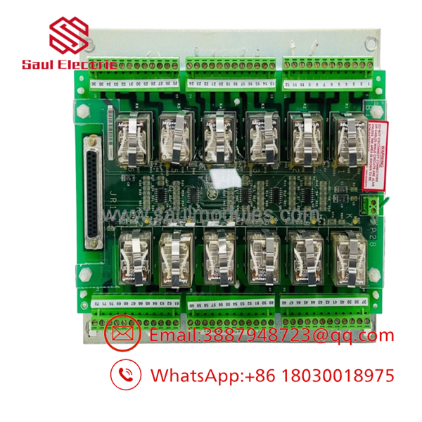
IS2020DRLYH1AA
The Veteran’s Tech Trap Guide
⚠️ Trap #1 — Do not confuse H1AA with H1BA.
The H1A and H1B DRLY variants have different relay-contact characteristics. The H1A version is associated with higher-power relay contacts, while H1B is intended for lower-power applications and hazardous-location requirements.
⚠️ Trap #2 — Don’t install it in the wrong mounting architecture.
This DRLY assembly is specifically identified as wall-mounted and intended for simplex operation. It should not be treated as a generic DIN-rail Mark VI terminal board.
PRO TIP: Photograph the original assembly, relay labels, 37-pin connector, field wiring, and mounting position before removal.
⚠️ Trap #3 — Check the field load before blaming the relay.
A relay contact may appear defective when the real problem is an overloaded contactor coil, shorted solenoid, incorrect suppression, or damaged field wiring.
Dynamic FAQ
What is the GE IS2020DRLYH1AA?
The is a GE Mark VI DRLY Relay Output Terminal Board used to provide relay-based discrete outputs. It contains 12 Form-C dry-contact relay outputs.
Is the IS2020DRLYH1AA a simplex or redundant module?
It is specifically intended for simplex applications. Available documentation states that only the simplex DRLY version is available.
How many relay outputs does it have?
The technical references identify 12 Form-C relay outputs. Up to two DRLY boards can be connected to the applicable processor arrangement, providing up to 24 contact outputs in that configuration.
Is IS2020DRLYH1AA interchangeable with IS2020DRLYH1BA?
Do not assume so. The H1A and H1B versions use different relay-contact designs, and the H1B version is associated with lower-power contacts and hazardous-location applications. Match the exact installed part number and system requirements.
How do I verify New Surplus authenticity?
Request photographs of the actual , including the identification label, relay area, connectors, and mounting assembly. Confirm whether it has ever been installed, repaired, rebuilt, or electrically tested.
What warranty information should I request?
Confirm the warranty period, DOA coverage, return conditions, and relay/contact test results. The supplier should clearly state whether the unit is New Surplus, Refurbished, or Used and identify the actual testing performed.




 Start Chat


