





Description
Key Technical Specifications
| Parameter | Value |
|---|---|
| Manufacturer | GE Multilin (GE Vernova) |
| Model | SR489-P1-HI-A20-E |
| Product Type | Generator Management Relay |
| Series | Multilin 489 |
| Protected Equipment | Small and medium synchronous or induction generators |
| CT Input | 1 A secondary (P1) |
| Control Power | 90–300 VDC or 70–265 VAC, 48–62 Hz |
| Analog Outputs | 4 programmable 4–20 mA outputs |
| RTD Inputs | Up to 12 RTD inputs |
| Digital Inputs | 8 programmable inputs |
| Relay Outputs | 6 programmable output relays |
| Communications | RS-232, RS-485, Ethernet (10Base-T) |
| Protocols | Modbus RTU, Modbus TCP, DNP3 |
| Protection Functions | 50/51, 27/59, 81, 87G, 40, 46, 32, 64G, 49, 25 and others |
| Mounting | Draw-out panel-mounted relay |
| Operating Temperature | Approximately -40 °C to +60 °C |
GE has officially discontinued the Multilin 489 product family and recommends the Multilin 889 as the replacement platform for new installations.
Product Introduction
The GE SR489-P1-HI-A20-E is a Multilin 489 Generator Management Relay developed for protecting and controlling small to medium-sized generators in power generation and industrial facilities. It combines generator protection, control, metering, diagnostics, event recording, and communications in a single draw-out relay package.
The relay supports comprehensive ANSI protection functions including differential protection, thermal overload, loss of excitation, overcurrent, voltage, frequency, and stator ground fault protection. Integrated communications and event recording simplify troubleshooting while reducing downtime during maintenance. Although the 489 is now a legacy product, it remains widely installed in power plants, cogeneration facilities, mining operations, and large industrial generator systems.
Troubleshooting Quick Reference
| Symptom | Possible Cause | Relevance to this Part | Quick Check Method | Recommendation |
|---|---|---|---|---|
| Relay will not power up | Missing control power | ❌ Low | Measure auxiliary supply (90–300 VDC / 70–265 VAC) | Verify supply before replacing relay |
| LCD powered but relay inactive | Internal power supply failure | ✅ High | Check diagnostic LEDs and self-test results | Replace relay if hardware failure is confirmed |
| Generator trips unexpectedly | Protection setting or CT wiring issue | ⚠️ Medium | Review event records and fault logs | Verify protection settings before hardware replacement |
| Differential protection operates | CT polarity or ratio mismatch | ⚠️ Medium | Compare CT secondary wiring and ratios | Correct wiring before replacing relay |
| Communication failure | Serial/Ethernet configuration error | ⚠️ Medium | Verify communication parameters and network status | Check cables and protocol settings |
| RTD alarms | Sensor wiring fault | ❌ Low | Measure RTD resistance and continuity | Verify field wiring |
| Analog output incorrect | Configuration or scaling issue | ⚠️ Medium | Measure 4–20 mA output with loop calibrator | Verify output mapping and scaling |
Field Tip: Many 489 relays removed from service are actually functioning correctly. In generator applications, CT polarity errors, incorrect relay settings, failed RTDs, or auxiliary power problems often produce symptoms that resemble relay failure. Before replacing the SR489, download the event recorder, review oscillography, and confirm all CT/VT wiring. Those checks typically identify the real source of the trip.
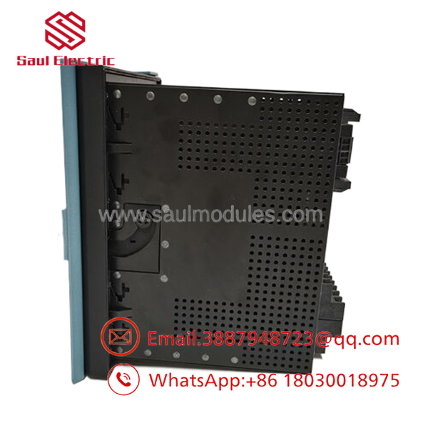
- SR489-P1-HI-A20-E
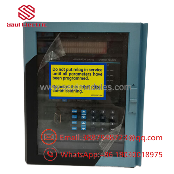
- SR489-P1-HI-A20-E
Frequently Asked Questions (FAQ)
Q1. What does the SR489-P1-HI-A20-E protect?
It is designed to protect small and medium synchronous and induction generators, providing electrical protection, monitoring, metering, event recording, and control.
Q2. What does the model code “P1-HI-A20-E” mean?
- P1: 1 A CT input
- HI: 90–300 VDC or 70–265 VAC auxiliary power
- A20: 4–20 mA analog outputs
- E: Enhanced LCD display
Q3. Is the Multilin 489 still manufactured?
No. GE Vernova lists the Multilin 489 as a legacy product and recommends the Multilin 889 for new installations and modernization projects. Existing units continue to be widely supported through surplus inventory.
Q4. Can I replace only the relay without changing the settings?
Not safely. Always back up the relay configuration, protection settings, logic, communications, and event records before replacement. Import the verified settings into the replacement unit before energizing the generator.
Q5. Why do many facilities still purchase New Surplus units?
Large power stations often maintain identical spare relays to minimize downtime. New Surplus units are genuine, unused OEM products sourced from excess inventory, making them a practical option for maintaining existing 489 installations after OEM discontinuation.
Q6. Does the relay support remote communications?
Yes. Depending on the installed hardware and configuration, the relay supports RS-232, RS-485, Ethernet, Modbus RTU, Modbus TCP, and DNP3, enabling integration with SCADA and plant control systems.
Q7. What should I verify before installation?
Experienced protection engineers recommend checking:
- Complete model number (SR489-P1-HI-A20-E)
- CT ratio and polarity
- VT wiring
- Auxiliary control power
- Protection settings
- Communication parameters
- Firmware revision compatibility
- Event recorder backup
- ESD precautions during installation
Performing these checks before commissioning helps prevent nuisance trips, minimizes startup delays, and ensures the relay operates correctly within the generator protection scheme.




 Start Chat


