





Description
Key Technical Specifications
| Parameter | Value |
|---|---|
| Manufacturer | GE / MTL Instruments |
| Model Number | 8910-PS-DC24V12VMTL |
| Product Type | DC System Power Supply Module |
| Input Voltage | 18.5–36 V DC (24 V DC nominal) |
| Output Voltage | 12 V DC ±5% |
| Maximum Output Current | 4.9–5 A |
| Output Power | Approximately 60 W |
| Input/Output Isolation | 50 V AC rms / 720 V DC continuous |
| Protection Features | Overload and short-circuit protection |
| Cooling | Natural convection |
| Mounting | Compatible carrier mounting |
| Operating Temperature | −40 °C to +70 °C (load dependent) |
| Weight | Approximately 0.78 kg |
| Application | Intrinsically Safe (IS) module power supply for MTL 8900 Series systems |
Product Introduction
The GE 8910-PS-DC24V12VMTL is a DC power supply module designed for the MTL 8900 Series intrinsically safe I/O platform. It converts a nominal 24 V DC input into a regulated 12 V DC output to supply field interface modules used in hazardous-area industrial automation systems.
In field installations for oil & gas, chemical processing, and process automation, this module is commonly selected because it supports redundant power configurations and stable operation in safety-related control cabinets. Before installation, verify carrier compatibility and available power capacity, particularly when replacing an older revision.
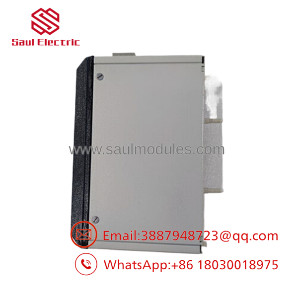
- 8910-PS-DC24V12VMTL
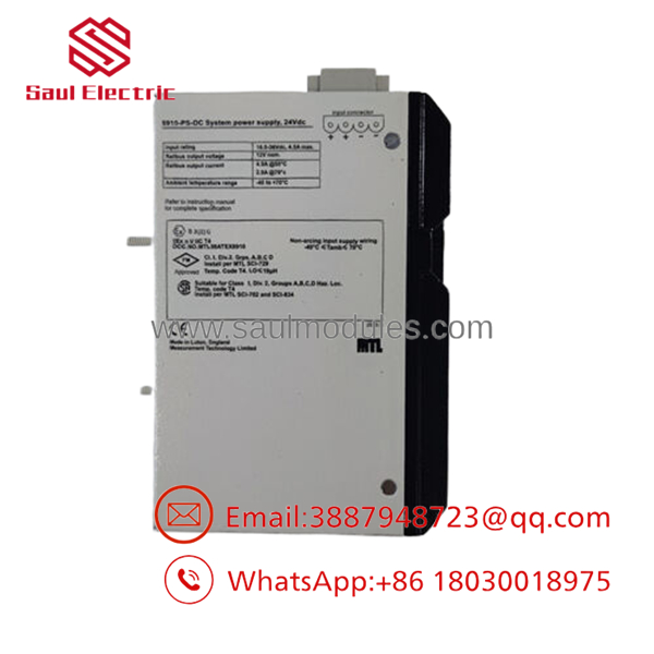
- 8910-PS-DC24V12VMTL
Troubleshooting Quick Reference
| Symptom | Possible Cause | Relevance to this Part | Quick Check Method | Recommendation |
|---|---|---|---|---|
| No output voltage | Missing 24 V DC input | ❌ Low | Measure input terminals with a Fluke 115 or equivalent | Verify upstream power supply first |
| Output below 12 V | Overloaded power supply | ✅ High | Measure output voltage under load | Reduce load or replace module |
| Power LED off | Internal power supply fault | ✅ High | Confirm correct input voltage and fuse condition | Replace module after confirming supply voltage |
| IS modules lose power | Carrier connection issue | ✅ High | Inspect carrier connectors and terminal screws | Reseat module and inspect carrier |
| Intermittent shutdown | Thermal overload | ✅ Medium | Measure cabinet temperature and inspect airflow | Improve ventilation and verify loading |
| Redundancy alarm | Secondary power supply failure | ✅ Medium | Verify load-sharing operation | Replace failed redundant supply |
| Frequent fuse operation | Short circuit on output | ❌ Low | Disconnect field load and re-test | Locate downstream fault before replacing module |
Technical Note: These power supplies are generally reliable. In most service calls, the actual cause is excessive load, wiring faults, or inadequate cabinet cooling rather than a failed power supply. If troubleshooting reaches a dead end, provide photos of the module label, LED indicators, wiring, and voltage measurements before ordering a replacement.
Frequently Asked Questions (FAQ)
Q1. Is the GE 8910-PS-DC24V12VMTL still manufactured?
No. It is considered a legacy industrial automation product. Most available inventory comes from New Surplus stock or professionally tested surplus inventory.
Q2. Can this power supply operate in redundant configurations?
Yes. The module supports load sharing when installed with a compatible redundant power arrangement, improving system availability during a power supply failure.
Q3. Can I replace the module while the system is energized?
To be honest, this depends on the carrier and system design.
Although some MTL systems support redundant exchange, always follow the OEM maintenance procedure. Never assume a module is hot-swappable unless your installation manual specifically states it.
Q4. Why should I verify the carrier model before ordering?
The power supply mates with specific MTL carrier assemblies. A matching electrical specification does not guarantee mechanical compatibility. Always confirm both the power supply part number and the carrier assembly.
Q5. Why is New Surplus inventory less expensive than buying directly from the manufacturer?
New Surplus inventory usually comes from canceled projects, excess OEM inventory, or unused maintenance stock. The module has not been installed in production service but is no longer supplied through normal factory production channels.
Q6. What warranty is typically available?
Most industrial automation suppliers provide a 12-month warranty for verified New Surplus or fully tested units. Request the functional test report before shipment whenever possible.
Quality Inspection & Testing SOP
1. Inbound Inspection & Traceability
- Verify OEM labels, serial numbers, and manufacturing identification.
- Inspect housing for scratches, corrosion, UV discoloration, and evidence of previous repair.
- Check terminal integrity and connector condition.
- Record serial numbers for complete traceability.
2. Live Functional Testing
- Install the module on an in-house MTL 8900 Series test carrier.
- Verify normal power-up and LED operation.
- Confirm regulated 12 V DC output under rated load.
- Perform continuous load testing for more than 24 hours while monitoring temperature.
- Generate a documented functional test report.
- Test photos and videos are available upon request.
3. Electrical Parameter Testing
- Measure insulation resistance using a 500 V Megger where applicable.
- Verify ground continuity.
- Measure input and output voltage using a calibrated Fluke digital multimeter.
- Confirm output stability under varying load conditions.
4. Firmware & Configuration Verification
- Not applicable for this power supply module.
- Verify hardware revision and manufacturing identification instead.
5. Final QC & Packaging
- QC inspector approval.
- Package inside an ESD-safe bag.
- Protect with bubble wrap and heavy-duty corrugated packaging.
- Apply a dated QC Passed label.
Technical Pitfalls & Survival Guide
❗ Verify the Input Voltage
This module expects a nominal 24 V DC input.
I’ve seen technicians accidentally connect higher-voltage cabinet supplies, destroying an otherwise healthy power module. Measure the input before energizing.
❗ Check Total Load
Adding extra IS modules without recalculating the total current demand is a common mistake.
Leave at least a 20% power margin to prevent nuisance shutdowns during peak load.
❗ Confirm Carrier Compatibility
Don’t assume every MTL carrier accepts the same power supply.
Verify the carrier part number before installation. Similar-looking carriers may use different power distribution arrangements.
❗ Inspect Terminal Tightness
Loose screw terminals create voltage drop and intermittent faults that look like a failing power supply.
Always torque field wiring according to the installation manual.
❗ Use Proper ESD Protection
I once watched a technician unpack a replacement module during winter without wearing an ESD strap. The module powered up once and never recovered.
Use a grounded wrist strap and place the module only on an ESD-safe surface.
Keep these checks in mind and you’ll avoid most installation mistakes, unnecessary replacements, and unexpected production downtime.



 Start Chat


