





Description
Introduction and Engineering Value
Digital output hardware converts control-system commands into discrete electrical signals used to operate field devices. The Honeywell CC-TDOB11 provides the terminal interface for a redundant Series C digital output arrangement based on the CC-PDOB01 module and a shared 24 VDC field supply.
For maintenance engineers, the important checks are the bussed output configuration, the connected field loads, and the required redundancy arrangement. The CC-TDOB11 is not a general-purpose relay output module; its compatibility and load limits must be verified against the installed module documentation.
Technical Specifications
| Specification | Details |
|---|---|
| Model | CC-TDOB11 |
| Part number commonly listed | 51308373-175 |
| Platform | Honeywell Experion PKS Series C |
| Assembly type | Digital output IOTA |
| Compatible module | CC-PDOB01 |
| Output architecture | Bussed 24 VDC |
| Output channel count | 32 |
| Configuration | Redundant |
| Nominal assembly length | 12 inches |
| Nonredundant option | CC-TDOB01 |
| Maximum field-load voltage | 30 VDC, according to a published technical listing |
| Maximum per-channel load current | 0.5 A, subject to the documented load and short-circuit conditions |
| Output protection | Overcurrent protection and fault indication are described in the Series C user guide |
| Installation requirements | Verify field-power distribution, load wiring, fusing, and module revision |
The channel count, nominal voltage, and redundancy configuration are consistent with the published Series C documentation. The current and voltage limits above must be checked against the applicable module specification and load conditions before engineering approval.
How the CC-TDOB11 works in the control system
The IOTA provides the physical terminal connections and field-power distribution interface for the digital output module. The CC-PDOB01 performs the output switching function. In a bussed arrangement, the field supply is distributed to output channels according to the module’s design.
Honeywell’s Series C user guide describes an overcurrent response for the 24 VDC digital output module: an affected output shuts down, its point enters Manual mode, and an overcurrent soft failure is generated until the short-circuit condition is corrected and proper current delivery is restored. Do not bypass the protection or treat an overcurrent alarm as proof that the IOTA itself has failed.
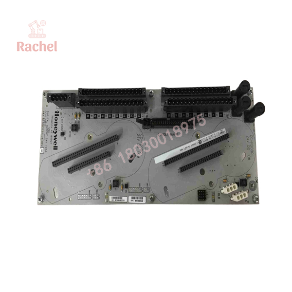
CC-TDOB11
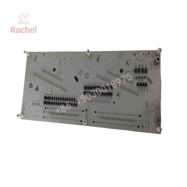
CC-TDOB11
Field Applications
The CC-TDOB11 is intended for compatible Series C digital output installations that require bussed 24 VDC signals and the designated redundant IOTA configuration.
- Solenoid valve control: Provides the terminal interface for compatible discrete output circuits controlling valve solenoids.
- Motor starter commands: Supports output wiring used for start/stop commands or other discrete control signals, subject to the interface and load requirements.
- Package equipment: Interfaces with discrete outputs for auxiliary skids, permissive signals, and equipment status-control sequences.
- Alarm annunciation: Supports discrete output connections for compatible annunciators and indication circuits.
- Redundant DCS maintenance: Provides a model-specific replacement option when the existing installation has been confirmed to use CC-TDOB11.
Illustrative maintenance scenario
During a planned shutdown, an output channel fails to energize a solenoid valve. The maintenance team checks the control command, module diagnostics, 24 VDC field supply, terminal wiring, fuse condition, and solenoid load. The team discovers a short circuit in the field wiring and corrects it before considering hardware replacement.
If inspection subsequently confirms that the terminal assembly also needs replacement, the team verifies the CC-TDOB11 label, CC-PDOB01 compatibility, and redundant cabinet arrangement. After installation, controlled functional tests confirm output behavior and associated diagnostics. This scenario is illustrative and does not represent a test performed on a particular unit.
QA and Testing SOP
Use the following checks when evaluating a replacement CC-TDOB11.
- Verify the model. Check the physical label for CC-TDOB11 and confirm the part number against the plant’s approved parts list.
- Confirm the I/O module. Verify that the installation uses the compatible CC-PDOB01 module and the correct Series C hardware revision.
- Check redundancy requirements. Confirm that the cabinet requires the redundant CC-TDOB11 rather than the nonredundant CC-TDOB01.
- Inspect the assembly. Look for damaged connectors, bent contacts, corrosion, contamination, damaged terminals, and signs of unauthorized repair.
- Verify field power and loads. Confirm supply voltage, wiring polarity, load current, terminal assignments, and fuse selection against the applicable documentation.
- Test protection behavior appropriately. Follow approved procedures for output status, diagnostics, and load checks. Never create an uncontrolled short circuit as a test method.
- Commission the installation. Verify the expected output state, field-device response, diagnostics, and redundancy behavior according to site procedures.
- Retain acceptance records. Document the model, condition, test scope, measured results, and any unresolved deviations.
Procurement note: New surplus, refurbished, and used units are distinct condition categories. Request a written condition declaration, label photographs, sourcing information where available, and unit-specific test records. A supplier listing alone does not prove authenticity, current availability, or successful functional testing.
Veteran’s Tech Trap Guide
Trap 1: Confusing CC-TDOB11 with CC-TDOB01
CC-TDOB11 is the redundant option; CC-TDOB01 is the nonredundant option. The installed cabinet layout and redundancy requirements determine the correct selection. Do not order based on the shared model prefix alone.
Trap 2: Ignoring the bussed field supply
A bussed output arrangement distributes a common field supply according to the module design. Check the load wiring, fuse selection, current limits, and short-circuit conditions before energizing the output channels.
Trap 3: Replacing hardware before isolating a field fault
An output that shuts down may be responding correctly to a short circuit or overload. Inspect the load and wiring, then review module diagnostics before concluding that the IOTA is defective.
Frequently Asked Questions
What is the Honeywell CC-TDOB11 used for?
It is a redundant Series C digital output IOTA used with the CC-PDOB01 module for bussed 24 VDC discrete output applications.
Is CC-TDOB11 compatible with CC-PDOB01?
Yes. Honeywell’s Universal Marshalling documentation lists CC-TDOB11 as one of the supported IOTA options for the CC-PDOB01 digital output module. Confirm the hardware revision and installation configuration before replacement.
What is the difference between CC-TDOB11 and CC-TDOB01?
CC-TDOB11 is the redundant IOTA option, while CC-TDOB01 is the nonredundant option. Both are associated with the CC-PDOB01 bussed 24 VDC digital output module, but they are intended for different system configurations.
How many output channels does CC-TDOB11 support?
The associated Series C digital output configuration supports 32 channels. The CC-TDOB11 is the terminal assembly; the compatible CC-PDOB01 module provides the output electronics.
What should be checked if a digital output channel shuts down?
Inspect the field wiring, connected load, field supply, fuse, and module diagnostics. Honeywell’s Series C documentation describes overcurrent protection that shuts down an affected output and reports a soft failure when a short-circuit condition is detected. Follow the applicable service procedure before restoring the channel.
How can I verify authenticity and warranty coverage?
Request clear photographs of the actual unit’s label, traceable sourcing information where available, and test records for the specific unit. Confirm the warranty period, return window, exclusions, and whether functional failures after installation are covered. Warranty terms vary by supplier and condition.

 Start Chat


