





Description
Core Product Summary
The Moog G122-824-002 is an analog P-I servo amplifier designed for closed-loop control applications that require proportional control, integral control, or a combination of both. It processes command and feedback signals to generate a configurable voltage or current output for a servovalve control loop.
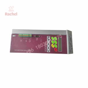
The module is designed for DIN rail mounting and provides front-panel adjustment potentiometers, LED indicators, and test points to support commissioning and troubleshooting. Compared with the earlier G122-824-001, the -002 version adds a 4–20 mA option at Input 2, an output-step push button, and improved thermal performance.
Key Technical Specifications
| Parameter | Specification |
|---|---|
| Manufacturer | Moog |
| Model | G122-824-002 |
| Product type | Analog P-I servo amplifier |
| Control modes | Proportional (P), integral (I), or P + I |
| Power supply | 24 VDC nominal; 22–28 VDC operating range |
| Command inputs | Two single-ended inputs |
| Feedback input | Differential input |
| Input 2 | Configurable for 4–20 mA or ±10 V |
| Feedback signal | Configurable for 4–20 mA or ±10 V |
| Output selection | Voltage or current, selectable |
| Voltage output | ±10 V |
| Current output | Selectable ranges from ±5 mA to ±50 mA |
| Maximum output current | Up to ±100 mA, subject to output configuration |
| Dither | Selectable, fixed 200 Hz |
| Mounting | DIN rail |
| Enclosure protection | IP20 |
| Operating temperature | 0 to +40°C |
| Dimensions | 100 mm W × 108 mm H × 45 mm D |
| Weight | Approximately 180 g |
Specifications are based on available G122-824-002 technical documentation. Confirm wiring, internal switch positions, output loading, and installed configuration against the applicable datasheet before commissioning.
Engineering Selection Highlights
- Selectable P, I, or P-I control: Allows the control strategy to be configured for the requirements of the application.
- Multiple analog signal options: Supports configured current or voltage signals for command and feedback paths.
- Adjustable loop parameters: Front-panel potentiometers provide access to proportional gain, integral gain, input scaling, feedback adjustment, and dither.
- Integrated feedback interface: A differential feedback input with zero and gain adjustment supports closed-loop control.
- Commissioning aids: LEDs and test points help technicians check internal supply status, valve-drive signals, and feedback amplifier output.
- Output-step function: The front-panel push button assists with loop optimization and was added in the -002 revision.
- DIN rail installation: The compact enclosure supports mounting in a suitable industrial control cabinet.
System Compatibility & Integration Requirements
The G122-824-002 is intended for analog servo-control systems. Its integration depends on the controller’s signal format, the feedback transducer, the servovalve’s electrical requirements, and the selected internal configuration.
Before installation, verify:
- The supply voltage is within the documented 22–28 VDC range.
- Command and feedback signals match the selected input configurations.
- The output mode and current range match the connected valve or load.
- The feedback transducer’s signal requirements and excitation needs are supported.
- The enable circuit, in-position output, grounding, and signal common are wired according to the applicable connection diagram.
- The existing control loop uses the correct pin assignments and internal switch settings for the G122-824-002.
Replacement caution: Do not assume that another Moog servo amplifier is a direct drop-in replacement based on function alone. A later model may use a different pinout or have different configuration requirements.
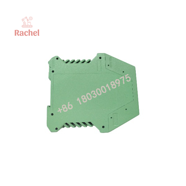
G122-824-002
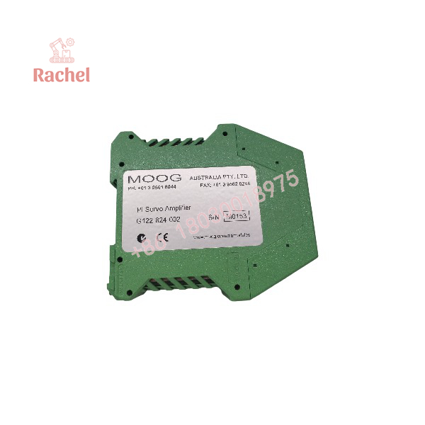
G122-824-002
Dimensions, Mounting & Connection Notes
The documented enclosure dimensions are approximately 100 × 108 × 45 mm (W × H × D), with DIN rail mounting and IP20 protection. Allow additional cabinet space for wiring access, terminal clearance, and heat dissipation.
The unit is an analog control module rather than a general-purpose PLC analog output card. Its inputs, feedback path, and output stage must be configured for the specific control loop.
IP20 protection does not provide protection against water ingress. Install the amplifier in a suitable enclosure and environment, and isolate power before changing wiring or internal switch settings. Refer to the product-specific application notes for the terminal layout and commissioning procedure.
Detailed Product Overview
The Moog G122-824-002 combines analog signal conditioning and P-I control in a compact DIN rail module. It accepts two single-ended inputs and one differential input. These signals are processed to form a control error, which is handled by the proportional and integral stages before reaching the configurable output amplifier.
Proportional control responds to the present error, while integral control accumulates error over time. Using either function individually or combining them allows the control engineer to tune the amplifier for the dynamics of the connected hydraulic system. Correct tuning depends on the valve, actuator, feedback transducer, hydraulic circuit, and mechanical load.
The amplifier includes adjustment potentiometers, status LEDs, and test points to support setup and fault diagnosis. Its selectable output stage accommodates voltage or current drive, subject to the module’s configured ranges and the load requirements. Dither can also be enabled or disabled according to application needs.
The G122-824-002 is a specific revision of the G122-824 series. Moog’s published revision notice identifies three differences from the G122-824-001: the additional 4–20 mA Input 2 option, an output-step push button, and improved thermal performance. When replacing an earlier unit, verify the wiring and application notes rather than assuming that all revision configurations are identical.
Applications & System Role
The G122-824-002 can be used in closed-loop systems where an analog P-I controller is required to drive a compatible electrohydraulic servovalve.
Typical application categories include:
- Hydraulic position control: Processes command and position-feedback signals within a configured servo loop.
- Pressure regulation: Applies proportional and integral control to a suitable pressure-control loop.
- Velocity control: Supports configured feedback and control signals for compatible motion systems.
- Industrial machinery: Provides analog servo amplification where the control design requires configurable P-I behavior.
- Turbine-related control applications: The -002 revision added a 4–20 mA Input 2 option, which Moog identified as enabling additional applications requiring 4–20 mA command and feedback signals. Actual suitability depends on the complete system design.
Frequently Asked Questions
What is the Moog G122-824-002 used for?
It is an analog P-I servo amplifier for closed-loop control applications, including systems that use electrohydraulic servovalves.
Does the G122-824-002 support 4–20 mA signals?
Yes. The documented configuration includes a 4–20 mA option at Input 2 and supports configurable 4–20 mA feedback. The actual signal setup must be checked against the unit’s configuration and wiring documentation.
What power supply does it require?
The technical datasheet specifies a nominal 24 VDC supply, with an operating range of 22–28 VDC.
Can the output be configured for voltage or current?
Yes. The output can be configured for voltage or current operation. The documented selections include ±10 V voltage output and selectable current ranges from ±5 mA to ±50 mA. Check the load requirements and module settings before connection.
What is the difference between G122-824-001 and G122-824-002?
Moog’s revision notice identifies a 4–20 mA Input 2 option, an output-step push button, and improved thermal performance as additions to the -002 version.
Is the G122-824-002 a PLC analog output module?
No. It is a dedicated servo amplifier with configurable control stages and a valve-drive output. It should not be treated as a general-purpose PLC analog output module.
What should be checked before replacing an installed unit?
Verify the complete model number, terminal wiring, supply voltage, input and feedback types, output mode, internal switch settings, and connected valve requirements. Confirm the replacement against the applicable technical documentation before energizing the system.

 Start Chat


