





Description
Core Product Summary
The Moog G122-829-001 (also referenced as G122-829A001) is a general-purpose, user-configurable Proportional-Integral (P-I) servoamplifier designed for closed-loop motion control and electrohydraulic valve drive applications. Operating on a 24 VDC supply voltage, the module accepts multiple analog command and feedback inputs to compute control error signals, outputting proportional and integral current or voltage drive signals to operate proportional and servovalves.
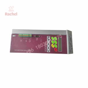
The module features three analog input channels—two differential inputs and one single-ended input—with switch-selectable signal ranges for 4–20 mA or ±10 V. The output stage can be configured via internal DIP switches for voltage output (±10 V into a minimum load of 200 Ω) or variable current output ranging from ±5 mA up to ±100 mA to suit various Moog servovalve coils. It is housed in a compact DIN rail-mounting enclosure with front-panel potentiometers, LED diagnostic indicators, test points, and an integrated step push button for closed-loop tuning.
Key Technical Specifications
| Parameter | Specification / Value |
|---|---|
| Product Type | Proportional-Integral (P-I) Servoamplifier |
| Manufacturer / Series | Moog / G122 Series |
| Model / Part Number | G122-829-001 (G122-829A001) |
| Supply Voltage | 24 VDC nominal (22 to 28 VDC) |
| Current Consumption | 75 mA @ 24 VDC (unloaded); 200 mA @ 24 VDC (at 100 mA load) |
| Control Modes | Proportional (P), Integral (I), or Combined (P & I) switch-selectable |
| Input Signals | Input 1: Single-ended (±10 V / command with selectable lag); Input 2: Differential (4–20 mA or ±10 V); Input 3: Direct summing input |
| Output Voltage Signal | ±10 V (minimum load resistance = 200 Ω) |
| Output Current Signal | Switch-selectable ±5, ±10, ±20, ±30, ±50 mA up to ±100 mA max |
| Transducer Excitation | +15 VDC and -15 VDC output for sensors |
| Terminal Wire Range | Screw terminals for 0.2 mm² to 2.5 mm² (24 AWG to 12 AWG) wire |
| Mounting | 35 mm DIN rail mounting (horizontal orientation recommended) |
| Enclosure Rating | IP20 |
| Module Weight | Approximately 0.18 kg (0.40 lbs) |
Detailed Product Overview
The Moog G122-829-001 serves as a signal conditioning and control amplifier within electrohydraulic closed-loop positioning, velocity, and pressure regulation systems. By housing analog computing elements inside a standalone DIN-rail enclosure, the G122-829-001 closes loop dynamics between feedback transducers (such as LVDTs, encoders, or pressure sensors) and hydraulic servovalves without relying on PLC scan-time dependencies.
The module incorporates internal DIP switches and plug-in resistor positions to configure loop behavior according to mechanical system requirements. Integrator routing can be switched between the primary error amplifier output or the amplified proportional stage, and an integrator limit feature prevents windup during large setpoint step changes or actuator mechanical limits.
For loop commissioning and troubleshooting, the front panel incorporates dedicated trim potentiometers for setting P gain, I gain, zero offset, input scaling, and dither amplitude. An integrated step push button injects a temporary -50% disturbance signal into the output stage, allowing field engineers to evaluate transient step responses and optimize loop stability directly from the module front panel.
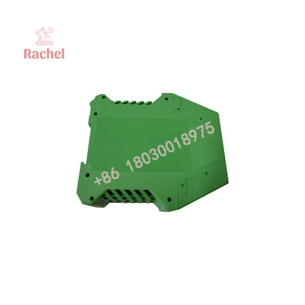
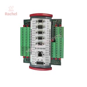
G122-829-001
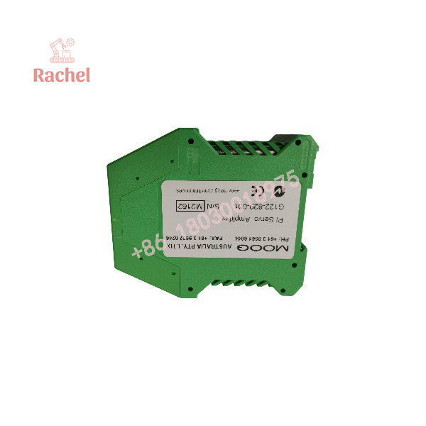
G122-829-001
System Compatibility & Integration Requirements
| Integration Item | Requirement / Compatibility Detail | Practical Note |
|---|---|---|
| Power Supply Protection | 24 VDC (22 to 28 VDC range) | In-series 250 mA T slow-blow fuse recommended on +24V input rail. |
| Compatible Servovalves | Moog proportional and servo valves up to ±100 mA drive current | Configurable output stage supports single-coil and dual-coil configurations. |
| Feedback Transducers | 4–20 mA or ±10 V feedback transmitters | On-board ±15 VDC supply terminals provide sensor excitation power. |
| Enable Input | +24 VDC enable signal | Drive output is disabled unless the enable terminal receives active 24 V logic. |
| In-Position Output | Active signal output | Indicates when loop error falls within pre-configured tolerance limits. |
Dimensions, Mounting & Connection Notes
- Mounting Orientation: Mount horizontally on a standard 35 mm DIN rail with the bottom rail release clip facing downwards to allow natural upward convection airflow through top and bottom enclosure vents.
- Wiring & Ferrules: Screw terminals accept wire sizes from 0.2 mm² to 2.5 mm² (24 AWG to 12 AWG). Crimp boot-lace ferrules are recommended for terminal connections.
- Service Cable Loop: Allow an extra 100 mm loop of wire length inside the enclosure so the internal circuit card can be unlatched and withdrawn from its housing while powered for switch adjustments.
- EMC Shielding: Use screened/shielded cables for all analog command and feedback wiring. Terminate cable shields to grounded enclosure cable glands or the module’s chassis ground terminal.
FAQ
What is the primary function of the Moog G122-829-001?
The Moog G122-829-001 is a DIN-rail mounted analog servoamplifier that provides closed-loop proportional and integral (P-I) control for electrohydraulic servo and proportional valves.
What power supply voltage does the G122-829-001 require?
The module requires a 24 VDC nominal supply voltage (operating range 22 to 28 VDC).
How is the valve drive output configured on the G122-829-001?
Internal selector switches allow the output stage to be configured for ±10 V voltage output or selectable current output levels up to ±100 mA.
What input signal formats are accepted by the servoamplifier?
The module features three inputs accepting standard ±10 V voltage signals or 4–20 mA current loop signals.
What is the purpose of the step push button on the front panel?
The front-panel step push button injects a momentary -50% output disturbance signal to assist engineers in tuning proportional and integral gains during system commissioning.

 Start Chat


