





Description
Product Introduction
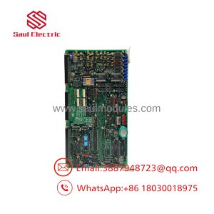
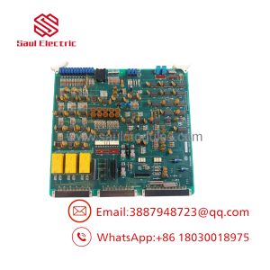
The NABCO (Nabtesco) FKC-108-O5 is a critical electronic controller PCB designed for shipboard main engine remote control systems, including the M-800-Z and MG-800 series. Mounted inside the main Engine Control Room (ECR) console or bridge maneuvering stand, this logic card processes telegraph orders, governor speed feedback, and safety interlock signals to coordinate pneumatic and hydraulic engine actuators on large 2-stroke diesel engines (such as MAN B&W and WinGD/Sulzer units).
Built specifically for high-reliability marine propulsion automation, the FKC-108-O5 handles hardwired signaling paths that bypass modern software-only architectures. Its conformal-coated circuit design insulates sensitive surface-mount ICs and bus transceivers against conductive salt mist, engine room humidity, and continuous vessel vibration. By isolating control loops, the module prevents localized electrical faults from knocking out the entire bridge control system.
Key Technical Specifications
| Parameter | Specification |
| Manufacturer | NABCO / Nabtesco Corporation |
| Part Number | FKC-108-O5 (Variant: FKC-108-05) |
| System Family | M-800 / MG-800 Main Engine Remote Control System |
| Input Supply | 24V DC Isolated Power Bus (System Rack Backplane) |
| Signal Inputs | Telegraph command positions, governor feedback, safety interlocks |
| Signal Outputs | Solenoid driver signals, E/P converter control, status relays |
| Mounting Style | Plug-in Card Guide / Eurocard Rack Assembly |
| Coating Type | Heavy-duty Marine Conformal PCB Coating |
| Operating Temperature | -10°C to +70°C |
| Vibration Resistance | Class-approved for high-vibration engine control rooms |
Application Scenarios & The “Trench” Experience
Picture this: The ship is maneuvering into a busy harbor with two tugs standing by. The captain moves the bridge lever to “Dead Slow Ahead,” but the telegraph alarm starts chiming continuously and the engine governor refuses to respond. In the ECR, the duty engineer sees a system bus fault LED lit on the remote control rack. An internal IC failure on the legacy logic card lost its speed setting signal handshake. Pulling the rack power, sliding out the failed PCB, and slotting in a pre-tested FKC-108-O5 replacement card brings the bridge telegraph back online in under ten minutes, avoiding a harbor collision risk.
- Commercial Ocean Vessels – ECR Console Racks – Processes telegraph position commands and translates them into voltage/current outputs for electro-pneumatic positioners.
- Bridge Maneuvering Stands – Speed Logic – Coordinates start/stop sequences and direction interlocks during harbor maneuvers.
- Ship Repower & Retrofit Projects – Legacy System Maintenance – Serves as a direct drop-in replacement card to maintain class certification without replacing entire console racks.
Field Case Study
A 180,000 DWT Capesize bulk carrier suffered an intermittent “Engine System Fail” fault while departing a port in Australia. The fault was traced to thermal stress cracking on an original FKC-108-O5 board installed back in 2008. The vessel couldn’t obtain sailing clearance until the remote control system proved 100% operational. A verified replacement card was hand-delivered to the ship overnight. The chief engineer set the onboard jumper configuration, seated the card into the M-800 sub-rack, and successfully completed sea-trial maneuvers within four hours.
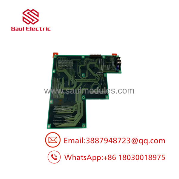
FKC-108-O5
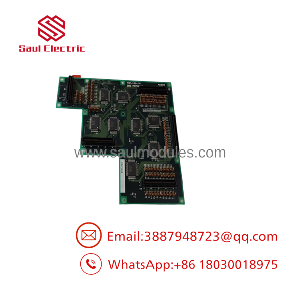
FKC-108-O5
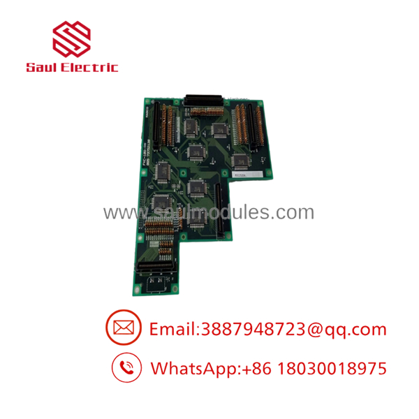
FKC-108-O5
Transparency SOP: Quality Assurance & Testing
We don’t just visually inspect circuit boards; we bench-test every card on physical power and logic simulators.
- Visual & Microscopic Inspection: Check edge connector contacts for wear, verify solder joint integrity, inspect for component bulging, and confirm genuine NABCO PCB silk-screening.
- 24V DC Power Conditioning: Apply power on test rigs while monitoring current draw and checking onboard voltage regulators for stable rail outputs.
- Logic Input/Output Tracing: Inject simulated lever command signals to verify that logic gates, optocouplers, and signal buses output the exact voltage states expected by downstream actuators.
- Conformal Coating & Insulation Inspection: Verify that the protective layer is intact and perform insulation resistance checks to ensure trace-to-ground isolation.
- Static Packaging: Wash edge connectors with contact cleaner, pack the card in static-shielding bags, and secure it in custom shock-absorbing foam boxes for ocean transit.
The Veteran’s Tech Trap Guide (Crucial Value-Add)
- ⚠️ Kill Rack Power Before Extraction: Never pull or seat an FKC-108-O5 card while the 24V DC rack power is live. “Hot-swapping” this card will create voltage transients across the backplane edge connector pins, which can fry adjacent signal processing chips on the board.
- ❗ Verify Onboard Jumpers / DIP Switches: Take a clear photo of your old card’s DIP switch states and hardware jumpers before removing it. Replacement FKC-108 cards often come with factory default settings that must be matched to your specific engine type (e.g., MAN B&W vs. Sulzer stroke logic).
- ⚠️ Clean the Rack Edge Connector: Before inserting the replacement card, inspect the female backplane slot inside the rack. Dirt, carbon dust, or oxidation inside the card guide can prevent a clean pin handshake, causing phantom alarms.
- ❗ Mind static electricity: Always wear a grounded ESD wrist strap when handling these boards. Unprotected human static discharges can punch invisible holes in logic IC gate oxides, leading to random system lockups weeks down the road.
Frequently Asked Questions (FAQ for Conversion)
Q: Does the require software programming or firmware flashing after installation?
A: No. The is a hardwired logic card. Configuration is handled entirely through hardware jumpers, DIP switches, and potentiometer trims on the board itself. No external laptop or software tool is needed.
Q: Are FKC-108-05 and the same part number?
A: Yes. Depending on the drawing office or marine spare parts manual, the letter “O” and the number “0” are used interchangeably in NABCO card designations.
Q: Can I use this card on a non-NABCO engine control system?
A: No. The pinout, backplane dimensions, and logic levels are engineered specifically for NABCO / Nabtesco M-800, MG-800, and related marine engine control racks.
Q: What is the primary cause of failure for these circuit boards onboard ships?
A: Heat buildup inside unventilated control consoles and persistent high-frequency vibration are the leading causes. Over time, heat dries out onboard electrolytic capacitors and vibration causes micro-fractures in solder joints.
Q: What warranty is provided with surplus NABCO circuit boards?
A: All cards are backed by a full 12-month functional replacement warranty from the delivery date.


 Start Chat


