





Description
Key Technical Specifications
| Parameter | Value |
| Product Type | PLC Analog Input/Output Module (S500) |
| Channels | 4 Analog Inputs / 4 Analog Outputs |
| Input Ranges | ±10 V, 0…20 mA, 4…20 mA, Pt100 (2/3-wire) |
| Output Ranges | ±10 V, 0…20 mA, 4…20 mA |
| Resolution | 12-Bit + sign |
| Rated Voltage | 24 V DC |
| Power Consumption | Max 5 W (0.15 A) |
| Isolation | Yes, between process and system voltage |
| Connection Type | Screw terminals (via TU515 or TU516 Terminal Units) |
| Dimensions (W x H x D) | 67.5 mm x 76 mm x 54 mm (excluding terminal unit) |
| Weight | 0.15 kg (0.33 lbs) |
| Operating Temperature | 0 to +60 °C (horizontal mounting) |
Product Introduction
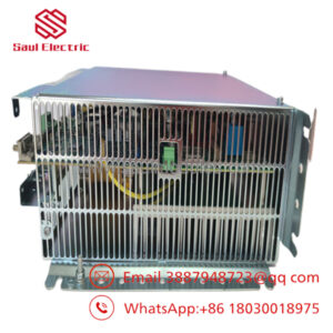
The ABB AX521 (1SAP250100R0001) is a highly versatile, multi-range analog input/output module designed for the ABB AC500 PLC platform and S500 I/O expansion racks. Featuring 4 analog inputs and 4 analog outputs on a single compact footprint, this module is specifically engineered to handle diverse field instrumentation, including temperature transmitters, control valves, variable frequency drives, and pressure transducers.
By integrating both high-accuracy inputs (supporting voltage, current, and Pt100 RTD sensors) and configurable outputs into one block, the AX521 reduces physical footprint constraints in control enclosures. This model serves as a standard, high-reliability replacement component for aging, critical processing systems across maritime, water treatment, and power generation sectors.
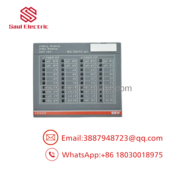
- 1SAP250100R0001
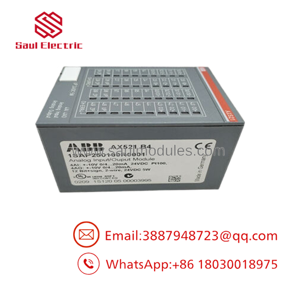
- 1SAP250100R0001
Installation & Configuration Guide
Stage 1: Pre-Installation Preparation (Estimated Time: 10 minutes)
- ⚠️ Safety First: Isolate the PLC rack power source. Verify using a calibrated multimeter (such as a Fluke 115) that no voltage remains on the 24 V DC distribution lines feeding the local terminal block. Follow standard lock out/tag out (LOTO) protocols for the enclosure.
- Tools Required: Grounded ESD wrist strap, PH1 screwdriver, fine-tip flathead screwdriver (for terminal block release), wire label makers.
- Data Backup: Before removing any faulty modules, back up the PLC application project via Automation Builder. Document the station IP address and hardware configuration settings on your active rack.
Stage 2: Removing the Old Module (Estimated Time: 5 minutes)
- Unplug the screw terminal block connectors from the module face. Do not pull on the individual copper conductors.
- Press the release latch located on the top of the terminal unit housing.
- Tilt the AX521 module slightly forward and slide it upward to clear the backplane connector guide rails.
- ⚠️ Note: Inspect the local backplane contact points on the terminal unit (e.g., TU515/516) for dust, corrosion, or physical damage. Keep the replaced module nearby for jumper verification.
Stage 3: Installing the New Module (Estimated Time: 10 minutes)
- Put on your grounded ESD wrist strap to protect the internal CMOS logic from static discharge.
- Configuration Clone: The AX521 configuration is primarily handled in software via Automation Builder. However, ensure that the address switches on the active Terminal Unit (if applicable to your remote I/O setup) are mapped correctly to prevent communication collisions.
- Align the new AX521 module with the guide slots on the terminal unit.
- Push downward and back until the module click-locks onto the DIN rail terminal unit.
- Re-insert the pre-labeled wiring terminal blocks. Ensure all screw terminals are torqued properly to prevent high-resistance contact points.
Self-Checklist:
- [ ] Module fully seated and locked onto terminal base
- [ ] Screw connections tight and matching original pin designations
- [ ] Terminal Unit address switches verified
Stage 4: Power-On & Testing (Estimated Time: 10 minutes)
- Perform a quick resistance check between the +24 V DC terminals and the ground rail to ensure no dead-shorts exist.
- Apply power to the PLC rack.
- Observe the LED diagnostic indicators on the front panel:
- PWR LED: Solid Green (Power is stable).
- ERR LED: Off (Red indicates a hardware fault or missing configuration parameter).
- Channel LEDs: Verify correct scaling/states during active sensor connection.
- Upload the system configuration and perform dry-run scaling tests on inputs/outputs using Automation Builder to verify loop signals.
- ⚠️ Troubleshooting Note: If the ERR LED flashes red continuously, verify that the module hardware version matches the physical profile defined in your Automation Builder software program.
Frequently Asked Questions (FAQ)
Can this module be hot-swapped while the PLC rack is powered?
No. The AX521 module is not designed for active hot-swapping under power on standard terminal units. Removing or inserting the module while the 24 V DC supply is active can cause electrical arching across the backplane pins, potentially corrupting backplane communications or permanently damaging the module’s internal circuitry. Always kill the rack power before swapping hardware.
Is the 1SAP250100R0001 obsolete, and is your inventory genuinely new?
The is still actively utilized worldwide, though finding factory-direct inventory can sometimes carry extended lead times. Our stock consists of 100% genuine, factory-sealed “New Surplus” or “New Original” parts sourced from excess project inventories and canceled engineering contracts. We back every unit with our own comprehensive 1-year replacement warranty.
If this model is temporarily out of stock, what is the direct replacement?
The (1SAP250100R0001) is the direct, standard module for this hardware profile. If it is completely unavailable, some integrators look to split the functionality into separate dedicated input and output cards (such as the AI523 and AO523) depending on space limitations. However, this requires significant modification of the physical wiring and a rebuild of the hardware configuration in your programming software. For direct drop-in replacement, we highly advise waiting for exact stock.
Will I lose my PLC’s program when I replace this I/O module?
No. The main control program is stored in the memory of the CPU module (such as a PM573 or PM583), not within this localized I/O module. Swapping this unit only interrupts active signal processing for its specific 4 analog inputs and 4 analog outputs. Once the physical swap is complete, the CPU will automatically push the scaling and parameters down to the new upon power-up.
Why is your price lower than the OEM standard factory list price?
We operate as an independent technical stockist specializing in surplus inventory distribution. Because we purchase unused industrial components in volume directly from canceled plant projects and system integrators’ excess stock, we do not pay wholesale markups. We pass those direct procurement savings on to you, offering the exact same genuine hardware at a fraction of standard lead times and manufacturer pricing.

 Start Chat


