





Description
Key Technical Specifications
The configuration code BM215AAAB specifies a precise hardware build, including specific I/O boards, analog input cards, and language options.
| Parameter | Value / Specification |
| Base Configuration Model | REM543 |
| Hardware Variant Code | BM215AAAB |
| Rated Frequency (f_n) | 50 Hz / 60 Hz (software selectable) |
| Auxiliary Supply Voltage | High-voltage variant nominal standard (typically 110–240 V AC/DC) |
| Analog Scaling Inputs | Conventional 1 A / 5 A current transformer and voltage transformer matching |
| Binary Channels (Digital I/O) | Multi-channel optoisolated input card with high-capacity power trip outputs |
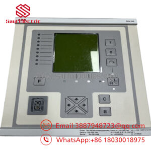
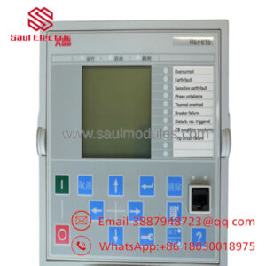
| HMI Interface | Built-in graphical LCD display with local control and alarm matrix |
| Communication Ports | Rear fiber-optic serial bus interface + Front optical programming port |
| Standard Testing Certifications | CE, UL listed, DNV/GL marine-certified options |
| Dimensions (W x H x D) | 223.7 mm x 249.8 mm x 235 mm (6U space profile) |
| Operating Temperature | −10 to +55 °C |
Product Introduction
The ABB REM543BM215AAAB is a highly specialized, microprocessor-based machine protection and control terminal engineered to safeguard large synchronous and asynchronous motors, generator units, and medium-scale industrial transformers. This specific alphanumeric configuration (BM215AAAB) establishes a precise hardware-to-software baseline, providing an optimized matrix of analog inputs, digital inputs, and industrial trip relays tailored for critical power grid and maritime engineering automation.
Rather than stacking disparate relays for thermal overload, differential fault, unbalance, and overcurrent conditions, the REM543BM215AAAB consolidates these parameters alongside programmable logic blocks within a compact 6U housing. This integration drastically reduces field panel wiring footprints, enhances deterministic trip-time speeds, and delivers robust diagnostic insights via its localized graphical HMI and upstream SCADA connectivity.
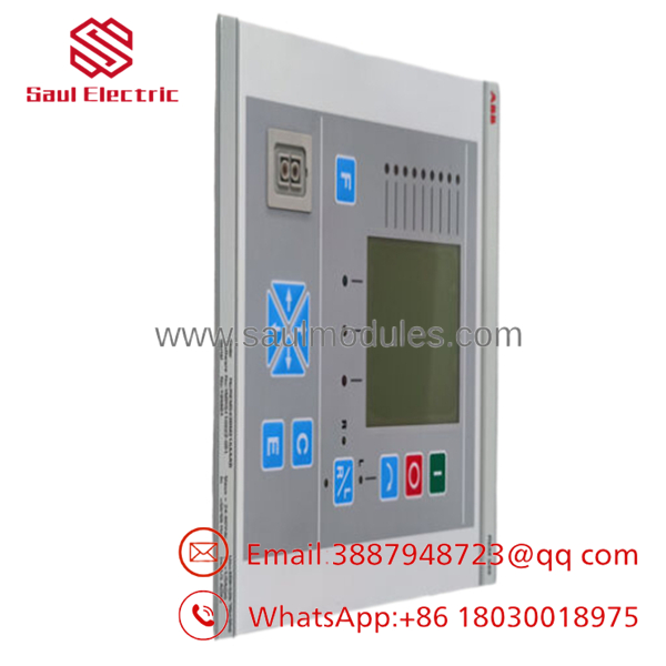
- REM543BM215AAAB
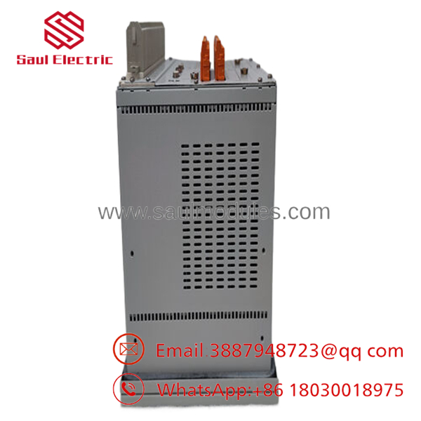
- REM543BM215AAAB
Troubleshooting Quick Reference
| Symptom | Possible Cause | Relevance to this Part | Quick Check Method | Recommendation |
| Green ‘Ready’ LED goes dark; screen is blank | Loss of primary control power or failure of internal PS1 board | ❌ Low to Medium | Using a Fluke 115 multimeter, measure incoming AC/DC voltage at power supply terminals X1.1. | If incoming power matches specs but the relay remains completely dead, the internal power conditioning card is shot. Replace the unit. |
| ‘Fault’ LED illuminates solid red | Checksum failure or critical internal hardware self-test fault | ✅ High | Perform a cold power cycle. Navigate via HMI buttons to Main Menu -> Diagnostics to read the specific internal error registers. |
Internal component defect. Swap out the terminal with a verified surplus module and restore your program code. |
| Phase currents read zero on HMI under active load | Open CT circuit loop or unseated analog card backplane connection | ❌ Low | Measure secondary current using a clip-on amp meter directly at the back screw terminals. Verify software CT scaling matches parameters. | If external current exists at the pins but reads zero in software, the internal analog transformer layer is damaged. Replace the terminal. |
| Intermittent communication drops to local SCADA | Fiber-optic attenuation or configuration mismatch in the communication card | ❌ Low to Medium | Check the rear communication card LEDs. Clean optical wire ends and verify that node address and baud rates match precisely. | If physical connection is sound, update protocol driver maps via CAP 505. Replace communication module if port is failed. |
Note: Always capture and archive complete disturbance recorder files and system status matrices before unmounting or performing a full field replacement of an active machine terminal.
Frequently Asked Questions (FAQ)
What does the explicit suffix “BM215AAAB” mean during a replacement? The string “BM215AAAB” is a factory-defined hardware configuration matrix code. It explicitly determines the number of active analog CT/VT channels, the voltage tolerances of the digital input boards, the layout of the power and signal relay outputs, the installed firmware capability profile, and the default HMI layout language. You must match this full alphanumeric string during a field replacement to ensure the physical backplane terminals accept your existing wiring harness without modification.
Can I download a configuration file from a generic REM543 directly into the REM543BM215AAAB? Only if the source terminal shared the identical hardware configuration matrix. If you attempt to force an execution file designed for an alternative module structure (e.g., a variant with different binary card slot alignments), the configuration tool will reject the transfer with a “Hardware Mismatch” flag or block certain digital mapping paths, rendering your custom interlocks non-functional.
Does this unit require CAP 505 or PCM600 software for field programming? The legacy REM543 series utilizes the CAP 505 or CAP 501 configuration and programming environment via an optical-to-serial communication cable connected to the front panel interface. The newer PCM600 platform is tailored for modern IED lines and will not natively program or handle mapping routines for this specific generation of protection relay terminals.
Why is New Surplus inventory preferred over local component repair for this specific relay? The REM543 series relies heavily on precision timing circuits, internal isolation transformer arrays, and surface-mount analog-to-digital converters to accurately track phase calculations. Local repair centers often swap out basic output relays or individual capacitors but cannot perform full-matrix dynamic injection tests or verify the precision of the trip algorithms under extreme load conditions. Our New Surplus inventory provides a clean factory baseline, ensuring completely uncompromised component integrity across every channel.
How long will the REM543BM215AAAB retain its programming in long-term storage? The device stores all user logic, protection curves, network settings, and hardware definitions within non-volatile EEPROM memory layers. This non-volatile storage doesn’t require constant power or active backup battery support to preserve its contents. The device can remain inside a storage facility for years without losing its core application files, though a system real-time clock adjustment will be necessary upon commissioning.

 Start Chat


