





Description
Key Technical Specifications
| Parameter | Value |
| Product Type | Digital Power Quality Analyzer / Network Analyzer |
| Mounting Type | Front-panel flush mounting (96 mm x 96 mm cutout) |
| Operational Voltage | Phase-to-Phase: 100…500 V AC / Phase-to-Neutral: 40…300 V AC |
| Current Inputs | Indirect measurement via 1 A or 5 A current transformers (CTs) |
| Auxiliary Power Supply | Multi-voltage 24…230 V AC/DC (operating ranges: 85…265 V AC / 90…300 V DC) |
| Communication Protocol | Modbus RTU via integrated RS485 port |
| On-board Outputs | 2 programmable digital outputs (pulse or alarm configurations) |
| Measurements Tracked | TRMS Voltage, Current, Frequency, Power Factor, Active/Reactive Power, THD, CO2/Euro conversion |
| Accuracy Class | Voltage & Current: ±0.5% / Power & Energy: ±1% (IEC 61557-12) |
| IP Rating | IP50 (front faceplate), IP20 (terminal connections) |
| Internal Depth | 57 mm (2.24″) inside the panel enclosure |
| Operating Temperature | -5 to +55 °C |
Product Introduction
The ABB 2CSG299893R4052 is a high-performance, front-panel mounted M2M MODBUS network analyzer designed for comprehensive power quality monitoring in low- and medium-voltage electrical switchboards. By tracking True RMS values of key electrical parameters including active/reactive energy, power factors, and Total Harmonic Distortion (THD), this digital meter delivers clear insights into local power quality.
Equipped with a built-in RS485 port supporting Modbus RTU communication, the 2CSG299893R4052 integrates easily with supervisory SCADA, DCS, or building management systems. Its compact 96×96 mm dimensions and removable terminal blocks simplify installation in crowded control panels, making it a reliable solution for energy audits and load management.
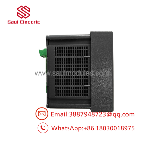
- 2CSG299893R4052
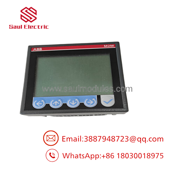
- 2CSG299893R4052
Installation & Configuration Guide
Stage 1: Pre-Installation Preparation (Estimated Time: 15 minutes)
- ⚠️ Safety First: Disconnect and lock out all upstream main voltage sources feeding the target distribution panel. Verify that the current transformer (CT) primary circuits are isolated and that CT secondary leads are safely short-circuited before working on the analyzer connections. Never open-circuit an energized CT secondary.
- Tools Required: PH1 and PH2 screwdrivers, small flathead terminal screwdriver, wire cutters/strippers, digital multimeter, and wire labels.
- Data Backup: Document the target system parameters: primary/secondary ratios of the installed current transformers (e.g., 500:5 or 100:1) and planned RS485 network communication settings (node address, baud rate, parity).
Stage 2: Removing the Old Module (Estimated Time: 10 minutes)
- Verify that all voltage measurement inputs are dead using a multimeter.
- Unplug the removable auxiliary power, RS485 communication, and digital output screw terminals from the back of the meter.
- Loosen and remove the side-mounting retention clips/hooks that clamp the analyzer chassis to the cutout frame.
- Carefully pull the meter forward out of the 96×96 mm panel opening.
- ⚠️ Note: If transferring the current transformer connections, ensure the CT shorting blocks remain closed throughout the removal process.
Stage 3: Installing the New Module (Estimated Time: 15 minutes)
- Slide the new 2CSG299893R4052 through the front of the 96×96 mm square panel cutout.
- Install the side-mounting plastic clips into their respective tracks on the meter housing. Tighten the screws evenly until the front gasket seals flatly against the panel face to achieve an IP50 seal.
- Configuration Clone: The M2M is configured via its front-panel keys. Before power-on, physically inspect the auxiliary power wiring to ensure it is connected to the designated V_{aux} terminals.
- Re-insert the pre-labeled terminal plugs. Pay close attention to current transformer polarity (S_1/K to input, S_2/L to common ground reference) to avoid inaccurate power factor readings.
Self-Checklist:
- [ ] Gasket sits flat against front door cutout, secured by side clips
- [ ] CT secondary grounding connections verified
- [ ] RS485 polarity (A(+) and B(-)) matches network bus standard
Stage 4: Power-On & Testing (Estimated Time: 15 minutes)
- Apply auxiliary power to the analyzer. The LCD display backlighting should turn on and begin its self-test boot cycle.
- Using the front interface buttons, navigate to the Settings Menu and immediately configure:
- CT Ratio: Match your physical current transformer parameters (e.g., set primary to 500 A if using 500/5 CTs).
- VT Ratio: If using voltage transformers, input the scaling ratio; leave at 1:1 if direct-connected.
- Communication: Set the Modbus network node address, baud rate (typically 9600 or 19200), and parity.
- Re-energize the main line voltage. Remove the CT secondary short-circuiting links.
- Observe phase-by-phase measurements to confirm reasonable, positive values for current and active power.
- ⚠️ Troubleshooting Note: If active power reads negative or the power factor is extremely low on a resistive load, check for reversed CT polarity on the backward channels.
Frequently Asked Questions (FAQ)
Can the current input terminal plugs be pulled while the primary line is running?
No, never pull the CT terminal block plugs while current is flowing through the primary system. Unplugging them creates an open-circuit state across the secondary windings of your current transformers. This produces extremely high voltage peaks across the open terminals, which can instantly destroy the meter, arc across adjacent electronics, and present a severe shock hazard to technicians. Always short-circuit the CT leads at a designated shorting block first.
Is the M2M MODBUS obsolete, and are these units genuinely new?
ABB has transitioned newer lines to the M4M series, making the legacy M2M MODBUS (2CSG299893R4052) increasingly difficult to procure directly from factory stock. Our units are “New Original/New Surplus” or certified “Refurbished,” sourced from excess system engineering packages. They are fully tested for accuracy on our testing rigs and carry our standard 1-year performance warranty.
What parameters must be configured before this meter registers accurate energy data?
For any power or energy values to be valid, you must program the correct Current Transformer (CT) primary and secondary rating. If you fail to configure the CT ratio, the meter defaults to reading current as a direct 5 A input, causing measurement values to be scaled incorrectly.
Will the M2M analyzer retain its energy counters if auxiliary power is lost?
Yes. The 2CSG299893R4052 features on-board non-volatile memory that automatically logs active, reactive, and apparent energy consumption indexes, alongside programmed configuration parameters. If auxiliary power drops out completely, no data will be lost; the accumulators will resume logging exactly where they left off once power returns.
Why is there a price variance between your stock and direct manufacturer listings?
By focusing on surplus and retired-but-unused project stocks, we bypass traditional distributor price floors and lead times. This allows us to supply high-demand legacy components directly to maintenance teams trying to keep older, approved panels online without going through costly, time-consuming panel redesigns.


 Start Chat


