





Description
Key Technical Specifications
| Parameter | Specification Value |
| Manufacturer | ABB |
| Model Number / Order Code | RLM01 / 3BDZ000398R1 |
| Interface Types | 3 x RS-485 (Line A, Line B, Line M) |
| Connectors | 9-pin Sub-D female interfaces |
| Transmission Rate | 9.6 kBit/s to 12 MBit/s (switch configurable) |
| Operating Voltage | 24 VDC (Acceptable range +20 to +33 VDC) |
| Current Consumption | 150 mA typical at 24 VDC |
| Power Loss | Approximately 3.6 W |
| Isolation Voltage | 500 Veff functional isolation per VDE 0110 |
| Alarm Signalling Contact | Potential-free contact, opens on fault (< 60 VDC, max 1 A) |
| Dimensions (H x W x D) | 134 x 56 x 70 mm |
| Mounting Configuration | 35 mm DIN standard rail |
| Environmental Protection | IP20 |
| Marine Certification | Germanischer Lloyd Type Approval (Category A, B, C, D) |
Product Introduction & Supply Chain Strategy
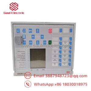
The ABB RLM01 is a specialized network infrastructure module that integrates single-interface PROFIBUS DP/FMS field instruments directly into redundant bus architectures. Operating as an active high-speed switch, the module takes a single master or slave line (Terminal M) and splits it into two completely independent, mutually redundant lines (Terminals A and B). It monitors signal amplitude, reconstructs wave forms via built-in repeater logic, and triggers a real-time hardware failover within 1-bit time if a line fault occurs.
Maintaining ABB RLM01 modules as New Surplus inventory is a paramount operational directive for facilities utilizing legacy distributed control configurations. Because refurbished network parts frequently suffer from latent chip aging or degraded optocouplers, they introduce dangerous data packet delay variations into the bus. Purchasing New Surplus hardware avoids these communication timeout risks, maintains network timing margins, and establishes a predictable 10-to-15-year lifecycle run without costly system re-engineering.
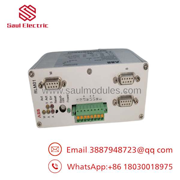
- RLM01
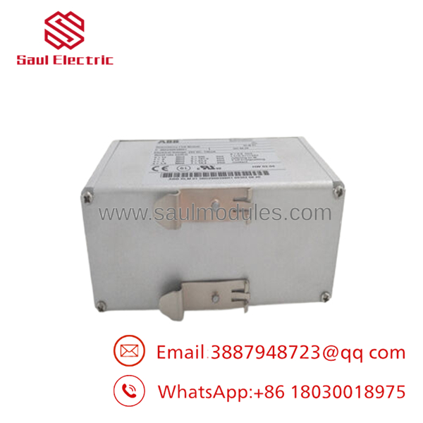
- RLM01
Installation & Configuration Guide
Stage 1: Pre-Installation (Prep & Safety)
- Power Isolation: De-energize the incoming 24 VDC power lines heading to the network rail destination.
- Static Countermeasures: Fasten a grounded ESD wrist strap to your wrist and attach the clip to the bare metal grid of the enclosure.
- Configuration Check: Locate the rotary or DIP switches on the side or front profile. Use a small screwdriver to set the network baud rate matching your existing PROFIBUS master configuration (e.g., Position 3 for 1.5 Mbit/s). Do not leave this to auto-detect if your bus cycle time is rigid.
Stage 2: Removal
- Unfasten the retaining screws on the three Sub-D connectors (A, B, and M) and slide the DB9 cables straight out to prevent pin misalignment.
- Pull off the 8-pin auxiliary terminal strip from the top or bottom of the housing.
- Release the DIN rail mounting tension spring by placing a flathead screwdriver into the lower release tab, then lift the module off the rail.
Stage 3: Installation (Clone & Seat)
- Hook the upper rear slot of the new ABB RLM01 onto the 35 mm DIN rail and press down firmly until the locking spring clicks into engagement.
- Verify that the cable shields are correctly grounded at the entry point of the cabinet panel.
- Plug the DB9 cables back into their matching designations: Line M connects to the non-redundant segment, while Line A and Line B run out to the redundant backbone paths. Secure the retaining screws.
- If this module resides at the definitive physical terminal point of the bus segment, ensure you activate the termination resistors built inside the fieldbus connectors.
Stage 4: Power-On & Testing
- Wire independent dual 24 VDC feeds to terminals L1+ and L2+ with their respective grounds to take full advantage of the internal power monitoring logic.
- Flip the upstream circuit breakers. Check that the green “L1+” and “L2+” power indicators remain steadily lit.
- Observe the line activity indicators. Correct operation shows flashing green or amber pulses corresponding to network telegram exchanges. If an error LED triggers, read the state of the potential-free fault contact at the 8-pin block to narrow down line attenuation faults.
Firmware/Software Versions & Upgrade Notes
The ABB functions entirely on the physical layer (Layer 1) of the OSI model. It is transparent to the data link protocol, meaning it lacks a native PROFIBUS station node address and requires no GSD file integration or active hardware parameters inside the hardware configuration tools.
However, network architecture teams must calculate transmission propagation delay properties. The internal repeater routing adds a deterministic data telegram delay equal to 11 bit times + 0.6 µs for paths moving A/B to M, and 4 bit times + 0.6 µs for paths moving M to A/B. When replacing a broken module with this New Surplus unit, you must verify that the slot time parameter configured within your PROFIBUS Master DP parameter matrix leaves a safe buffer for this cumulative internal hardware propagation delay.
Frequently Asked Questions (FAQ)
Q: This module is listed as obsolete by the factory. Can I safely replace it with the newer RLM02 version?
A: While the RLM02 is an updated release, its physical dimensions, mounting clearances, and internal telegram delay timings differ slightly from the legacy ABB . Swapping to an RLM02 could require changes to your bus parameter calculations or mechanical layout adjustments. Installing an exact New Surplus allows for an immediate swap with zero changes to your physical panel or network properties.
A: Used modules are susceptible to optocoupler degradation and power trace degradation caused by running 24/7 in hot electrical enclosures. This wear degrades the rise and fall times of the RS-485 square waves, leading to intermittent cyclic redundancy check (CRC) errors and unprovoked bus failovers. Our New Surplus inventory circumvents these hidden component wear issues completely.
Q: Does this module allow me to couple two completely separate non-synchronized masters?
A: No. The ABB is engineered for line redundancy, not master redundancy. The incoming data streams on lines A and B must come from synchronous sources. If you attempt to feed asynchronous lines into A and B, the random internal selection logic will fail and corrupt your communication frame boundaries.
Q: Can I run the unit with only a single 24 VDC power supply feed?
A: Yes, the module will operate with a single supply on terminal L1+. However, if you do not run a second source to L2+, you must place a wire jumper from L1+ to L2+ to bypass the internal power supply monitoring logic. If left unjumpered, the module will continuously flag a power fault error condition and trip the diagnostic alarm contact.
Q: How does the module select which line to use if data arrives at both A and B simultaneously?
A: If valid frames land at precisely the same time on both line entries, the internal high-speed control logic picks line A or line B randomly based on the first detected character edge. If that active selection encounters a bad start delimiter or packet fault later in the stream, the control logic immediately reroutes to the remaining healthy path.
If you need help confirming your system settings, I can calculate the precise PROFIBUS slot time changes required for your specific baud rate when adding this hardware. Would you like me to generate that calculation?

 Start Chat


