





Description
Key Technical Specifications
| Parameter | Value |
| Product Type | Integrated Gate-Commutated Thyristor (IGCT) |
| Repetitive Peak Off-state Voltage (V_{DRM}) | 4,500 V |
| Silicon Wafer Diameter | 91 mm |
| Gate-Drive Inductance | ≤ 6 nH (achieved via coaxial gate feed) |
| Turn-off Speed (dI_G/dt) | ≥ 3,000 A/µs (at 3 kA switching load) |
| Gate Drive Voltage | -20 V nominal (safe limit after turn-off) |
| Control Interface | Fiber-optic communication link |
| Application Environment | ACS 6000 and ACS 5000 MV Drive Converters |
| Physical Dimensions | 350 mm x 290 mm x 60 mm (13.8″ x 11.4″ x 2.4″) |
| Product Net Weight | 2.64 kg (5.82 lbs) |
| Operating Temperature | -40 to +70 °C (ambient storage, liquid/heatsink cooled in operation) |
Product Introduction
The ABB 5SHY4045L0004 (3BHB021400R0002) is a highly specialized Integrated Gate-Commutated Thyristor (IGCT) module engineered for high-power industrial applications, such as the ABB ACS 6000 medium voltage drive family. This device combines the low on-state losses of a thyristor with the fast, predictable switching characteristics of a modern transistor.
By integrating a low-inductance, multi-layer gate drive directly onto the semiconductor housing, the 5SHY4045L0004 allows fast transition times, preventing the silicon wafer from entering unstable thermal zones during turn-off. It serves as a vital replacement power-switching element in heavy industries like metal rolling mills, marine propulsion, water pumping stations, and wind power generation systems.
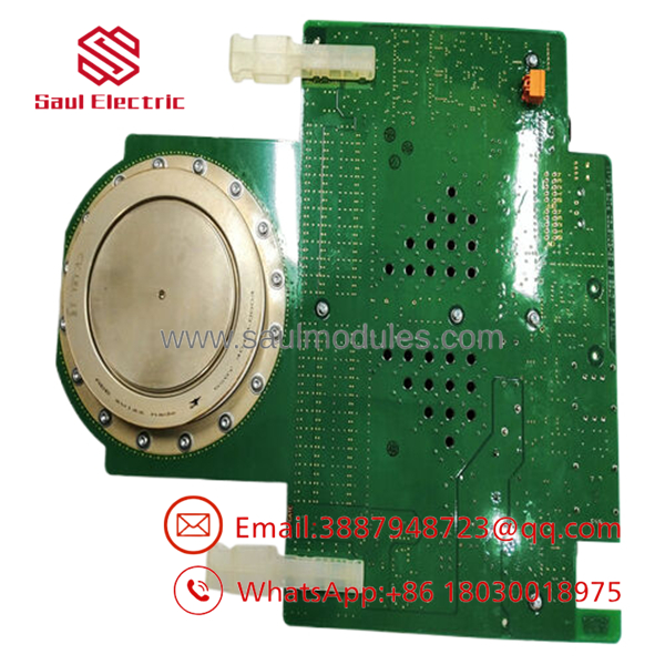
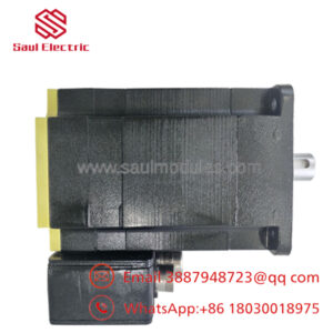
- 3BHB021400R0002 5SHY4045L0004
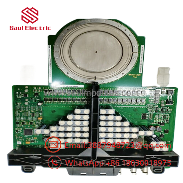
- 3BHB021400R0002 5SHY4045L0004
Installation & Configuration Guide
Stage 1: Pre-Installation Preparation (Estimated Time: 20 minutes)
- ⚠️ Safety First: High-power medium voltage drives (typically 3.3 kV to 6.9 kV) contain massive, lethal stored capacitive energy. Isolate all upstream medium voltage supply breakers. Wait at least 15 to 20 minutes for the DC link capacitors to discharge. Connect the standard safety grounding rods to the DC busbars. Verify with a calibrated high-voltage proximity detector that the cabinet is completely de-energized.
- Tools Required: Grounded ESD wrist strap, torque-wrench with insulated socket adapters, fiber-optic cleaning tool, lint-free wipes, high-vacuum grease (or thermal contact paste).
- Data Backup: No parameters reside directly on this thyristor card, but it is advised to back up the main converter application and active error log using DriveComposer Pro or your designated ABB commissioning tool prior to servicing.
Stage 2: Removing the Old Module (Estimated Time: 10 minutes)
- Disconnect the auxiliary 24 V DC power cable plug feeding the integrated gate board.
- Unplug the fiber-optic control lines (both RX and TX paths) from the optical transceivers. Immediately put protective dust caps on the fiber tips and ports.
- Loosen the clamp tension mechanism that holds the semiconductor wafer sandwich between the heat sinks.
- Gently slide the complete 5SHY4045L0004 module out of the phase-leg stack assembly.
- ⚠️ Note: Avoid touching the bare metal poles of the semiconductor disk. Keep the assembly flat on a clean, anti-static work bench.
Stage 3: Installing the New Module (Estimated Time: 15 minutes)
- Wear a grounded ESD wrist strap before unboxing the new 3BHB021400R0002 module.
- Inspect both physical faces of the 91 mm silicon housing for deep scratches or pitting. Clean the contact faces using lint-free wipes and electronic solvent.
- Apply an extremely thin, uniform layer of specialized contact paste to both the cathode and anode faces to optimize electrical and thermal conductivity.
- Slide the module into the phase-leg stack assembly, ensuring the polarity markers (Anode/Cathode) correspond to the schematic orientation.
- Re-tighten the stack clamping assembly using a torque wrench. Strictly adhere to the OEM clamping force specifications (typically around 30 to 40 kN); under-tightening causes high-resistance hot spots, while over-tightening fractures the internal silicon wafer.
- Connect the auxiliary power cables and carefully plug the fiber-optic lines back into their color-coded transceiver sockets.
Self-Checklist:
- [ ] Clamping force of the phase-leg stack verified via torque gauge
- [ ] Fiber-optic links inserted until they click securely
- [ ] Thermal grease applied smoothly without excess buildup
Stage 4: Power-On & Testing (Estimated Time: 20 minutes)
- Ensure all tools and grounding rods are removed from the drive cubicle. Secure all safety enclosure doors.
- Apply the auxiliary control voltage to power up the converter control system (leaving the main MV grid disconnected).
- Observe the green LED indicators on the 5SHY4045L0004 gate-drive board; a steady green status confirms the integrated gate drive is healthy and receiving its -20 V bias.
- Verify that no active gate-driver or fiber-optic communication faults exist on the drive’s master control unit.
- Execute a gate-drive test sequence (pulse-test) via the service software to verify correct switching operations under control-level power.
- ⚠️ Troubleshooting Note: If a “Gate-Unit Fault” is logged, check the supply voltage at the auxiliary terminal plug. Low supply voltage will prevent the gate drive from maintaining the necessary dI_G/dt turn-off rate.
Frequently Asked Questions (FAQ)
What is the function of the integrated board on the 5SHY4045L0004?
The circuit board physically attached to the semiconductor wafer is the integrated gate drive unit. It is necessary because turning off an IGCT requires pulling thousands of amperes out of the gate in less than 1 microsecond. To achieve this, the drive unit must reside directly adjacent to the silicon disc, minimizing gate inductance to less than 6 nH and preventing the silicon from overheating during switching cycles.
Can I handle this module without an ESD strap since it’s a heavy power component?
Absolutely not. While the thyristor disc itself handles thousands of volts, the integrated gate drive circuit contains sensitive, high-speed CMOS control chips and optocouplers that can be instantly damaged by static electricity. Always wear a grounded ESD wrist strap when unpacking or installing the module.
Why is the clamping force so critical during mechanical installation?
The internal silicon wafer is held against its electrical contacts strictly by mechanical pressure. If the clamping force is too low, electrical resistance rises, causing rapid overheating and catastrophic failure under load. If the force is too high, the physical wafer will crack. Always use a calibrated tension clamping rig matching the specified kilonewtons (kN) on the ABB datasheet.
What is the difference between an IGCT and a standard GTO thyristor?
An IGCT (Integrated Gate-Commutated Thyristor) has a significantly faster gate commutation time compared to a legacy Gate Turn-Off (GTO) thyristor. By integrating a low-inductance gate unit directly onto the semiconductor package, the cathode current is turned off instantly (typically under 1 µs), allowing the device to operate with much lower switching losses and without complex snubber circuits.
Do I need to perform any software configuration when replacing this module?
No. The 5SHY4045L0004 behaves purely as a physical switching component. The control and timing profiles are dictated by the drive controller board. As long as the hardware ratings, optical parameters, and part numbers match, the drive will run immediately after installation without parameter alterations.


 Start Chat


