





Description
Key Technical Specifications
| Parameter | Value |
| Product Type | Thyristor / SCR / IGCT Gate Control Board |
| Model Designation | GVC736CE101 |
| System Power Grid Compatibility | Designed for medium and high-voltage converters (up to 3,300 V / 4,500 V applications) |
| Auxiliary Supply Input | 24 V DC (limits: ±10%) |
| Control Signal Interface | High-speed fiber-optic links (TX/RX transceivers) |
| Switching Performance | Low propagation delay, high dI_G/dt support |
| Circuit Board Features | Conformal coated, high-temperature components, integrated overcurrent/overvoltage protection |
| Mounting Configuration | Direct-mount to power semiconductor stack or sub-chassis baseplate |
| Operating Temperature | -40 to +85 °C |
| Storage Temperature | -40 to +85 °C |
Product Introduction
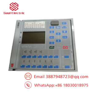
The ABB GVC736CE101 (3BHB045647R0001) is an advanced gate-driver and interface control card engineered for heavy-duty power electronics applications. It acts as the critical high-speed intermediary between the main controller (such as an AC 800M or similar drive controller) and physical power semiconductor switching modules—specifically Silicon Controlled Rectifiers (SCRs), thyristor stacks, and Integrated Gate-Commutated Thyristors (IGCTs).
This board converts high-level optical command pulses into precise, high-current electrical gate triggers, ensuring instant turn-on and turn-off transitions. This control minimises thermal losses across switching junctions. Equipped with onboard protection circuits and fast optical interfaces, the GVC736CE101 is commonly used in medium-voltage variable frequency drives (like the ACS6000), excitation systems (like the UNITROL 6000 series), and high-capacity industrial rectifiers.
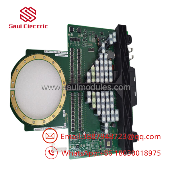
- 3BHB045647R0001
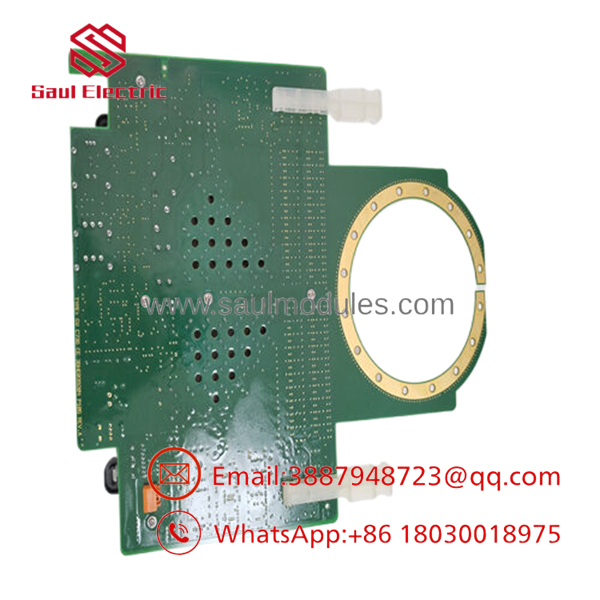
- 3BHB045647R0001
Installation & Configuration Guide
Stage 1: Pre-Installation Preparation (Estimated Time: 20 minutes)
- ⚠️ Safety First: Medium- and high-voltage power electronics compartments contain highly lethal residual electrical charges in their DC link capacitors. Isolate the main three-phase line breakers. Wait at least 15 to 20 minutes for capacitors to fully discharge. Use a calibrated high-voltage proximity detector to verify the cabinet’s internal power bars are dead. Bond safety grounding cables to the system before starting physical work.
- Tools Required: ESD grounded wrist strap, standard electronic screwdrivers, insulated socket wrench set, fiber-optic diagnostic cleaner, and lint-free wipes.
- Data Backup: The GVC736CE101 handles physical hardware triggering. No system parameter profiles are stored directly on this board. However, backing up the master controller’s parameters via DriveComposer or Control Builder before power-down is highly recommended.
Stage 2: Removing the Old Module (Estimated Time: 10 minutes)
- Turn off the auxiliary 24 V DC control power distribution circuit feeding the board.
- Put on your grounded ESD wrist strap. Attach the ground clip to the designated chassis grounding rail.
- Carefully disconnect the incoming fiber-optic signal lines from the board’s optical transceivers. Immediately apply protective dust caps to the fiber-optic cable ends and board transceivers.
- Unplug the multi-conductor gate-trigger harness and power input plugs.
- Remove the mounting screws securing the board to the semiconductor assembly or sub-chassis plate. Remove the GVC736CE101.
Stage 3: Installing the New Module (Estimated Time: 15 minutes)
- Unpack the new GVC736CE101 (3BHB045647R0001) on an anti-static surface while wearing your ESD wrist strap.
- Align the mounting holes of the board with the standoffs on the semiconductor frame.
- Secure the board using its native screws. Do not over-torque to prevent cracking the multi-layer printed circuit board (PCB).
- Connect the physical power and gate-trigger wiring harnesses. Verify that all plug connectors lock firmly into place.
- Clean the fiber-optic cable tips using an optical cleaning tool, remove the dust caps, and plug them into their respective RX/TX sockets.
Self-Checklist:
- [ ] board physically secured without mechanical stress on the PCB
- [ ] Fiber-optic connections clean and snapped into place
- [ ] Aux power polarity verified at the input terminals
Stage 4: Power-On & Testing (Estimated Time: 15 minutes)
- Verify that all physical tools and loose materials have been removed from the cabinet. Close the safety enclosures.
- Restore the 24 V DC auxiliary control power (leave the medium/high-voltage main power isolated).
- Check the onboard LED status indicators. Solid green represents nominal diagnostic power, while red indicates a local trigger interface fault.
- Verify that no active gate-unit or communication-link faults are present on the system operator panel.
- If available, run an off-line pulse test via the control software to confirm successful gate triggering.
- Once confirmed, remove the temporary safety ground bonds, re-energize the primary high-voltage line power, and resume normal operation.
Frequently Asked Questions (FAQ)
What is the difference between and other GVC736 variants?
The suffix CE101 indicates the specific revision, terminal design, and component mapping of the GVC736 gate control platform. While some variants share similar structural blueprints, swapping revisions without verifying compatibility with the master converter’s controller firmware is not recommended. Always verify the exact part number 3BHB045647R0001 matches your existing unit.
Can this board be replaced without turning off the system?
No. The operates directly adjacent to high-power, high-voltage circuits. Attempting to replace this board while any part of the system is energized is highly dangerous. Doing so can cause fatal electrical shock, catastrophic short circuits, or severe arc flashes. Always follow standard lock out/tag out (LOTO) protocols before servicing.
Why is cleanliness so important for the fiber-optic connections?
The utilizes high-speed fiber-optic links to receive triggering commands from the system’s central controller. This optical link isolation protects low-voltage electronics from high-voltage transients. Even minor dust particles or grease on the optical faces can degrade the light signal, causing transmission errors, erratic thyristor switching, and unexpected drive tripping.
Is the conformal-coated for extreme environments?
Yes. ABB designs these high-power interface boards with advanced industrial-grade conformal coating. This protective layer shields the board’s surface-mount components and trace layouts from conductive dust, humidity, and chemical vapors typical in metal mills, offshore platforms, and chemical processing plants.
What is the typical reason for a GVC736 gate unit fault indication?
Most gate unit faults stem from unstable 24 V DC auxiliary control power, damaged or bent fiber-optic links, or a failing power semiconductor (SCR/thyristor/IGCT) creating high back-EMF feedback. If a fault is displayed, first measure the incoming 24 V auxiliary voltage and inspect the physical condition of the optical fiber.

 Start Chat


