





Description
Key Technical Specifications
| Parameter | Value |
| Brand | ABB |
| Model Number | PCD235A101 |
| Global Product ID | 3BHE032025R0101 |
| System Architecture | Unitrol Series (6000 / Light) / Power Electronics Controller (PEC) |
| Power Supply | 24 V DC Nominal (Dual redundant inputs: X1 and X2) |
| Communication Protocol | Modbus RTU via DB9 / Dedicated serial interface (X65) |
| Diagnostic Indicators | LED Arrays: Fault (F), Run (R), Power (P), Alarm (A) |
| Enclosure Type | Shielded, ventilated steel-plated chassis |
| Mounting Orientation | Integrated control rack panel / Baseplate mounting |
| Net Weight | 1.85 kg |
| Country of Origin | Switzerland (CH) |
Product Introduction
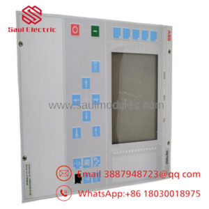
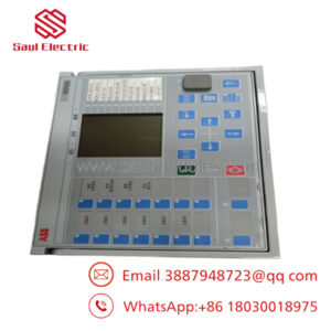
The ABB 3BHE032025R0101 PCD235A101 is an advanced processing and serial communication interface module operating on ABB’s high-performance Power Electronics Controller platform. Built primarily for large-scale power generation and drive control frameworks—such as Unitrol excitation systems and high-capacity synchronous motor controllers—the PCD235A101 functions as a central diagnostic and telemetry hub. It bridges the gap between ultra-fast internal control loops and external SCADA or plant-wide Distributed Control Systems (DCS).
The module’s architecture stands out for its high noise immunity and real-time processing capabilities. By deploying a dedicated serial engine alongside dual, isolated 24 V DC power terminals (labeled X1 and X2), it maintains reliable link operation even during heavy power transients or structural grid disturbances. The front-mounted diagnostic array provides operators with immediate visual confirmation of the unit’s operational health, identifying internal processing faults before they lead to unexpected system trips.
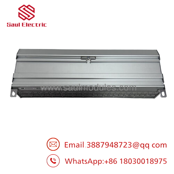
- 3BHE032025R0101 PCD235A101
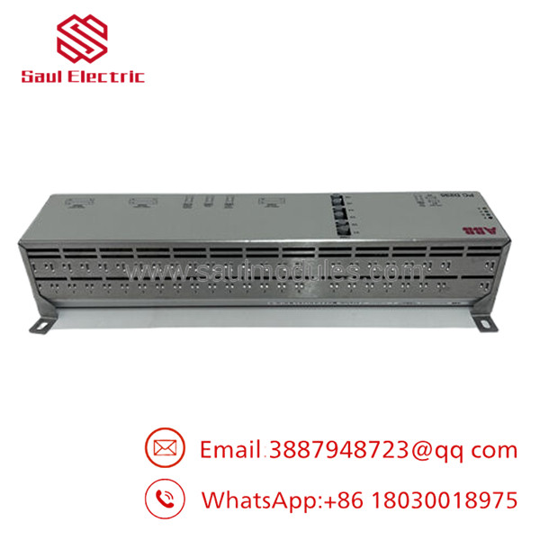
- 3BHE032025R0101 PCD235A101
Installation & Configuration Guide
1.System Lockout & Environmental Prep:Estimated time: 10 mins.
De-energize the entire control enclosure. Ensure the Unitrol excitation cubicle or motor drive system main breaker is locked and tagged out. Verify using a calibrated multimeter that no residual high voltage remains on adjacent terminals.
Ensure the installation area is completely free of metallic dust, humidity, or moisture. Don an ESD grounding wrist strap and connect its clamp to an unpainted, structural ground point on the subpanel frame.
2.Mechanical Mounting:Estimated time: 15 mins.
Align the PCD235A101 module with the matching chassis mounting holes on the master subpanel baseplate. Avoid touching any exposed internal components or board traces along the lower edge.
Hand-start all mounting screws to prevent cross-threading. Secure the module using a cross-tightening pattern, torquing the chassis screws precisely to the recommended mechanical holding specifications. Verify that the ventilated metal cover is unblocked to ensure adequate passive air cooling convective flow.
3.Electrical Wire Termination:Estimated time: 15 mins.
Redundant 24V DC Input Wiring: Route dual, independent 24 V DC power source feeds to the green terminal blocks. Wire the primary power supply to Terminal X1 (Pins 1 and 2) and the backup supply line to Terminal X2 (Pins 3 and 4), verifying correct plus/minus polarity mapping.
Communication Cable Routing: Plug the system serial or Modbus cable into the dedicated DB9 connector or the designated X65 interface port. Secure the DB9 thumb screws finger-tight. Ensure the communication cable’s outer shield is grounded correctly at the entry point of the cubicle to prevent electrical noise induction.
Pre-Power Checklist:
- [ ] Redundant X1 and X2 power sources have verified correct polarity.
- [ ] Communication cables are physically isolated from high-voltage AC phase cables.
- [ ] The module chassis has a solid metal-to-metal grounding contact path.
4.Initial Power-Up & LED Verification:Estimated time: 15 mins.
Clear the enclosure of all tools. Close the cabinet doors and re-energize the auxiliary 24 V DC distribution circuit breakers.
Observe the LED diagnostic array on the front panel face:
- P (Power): Should light up steady Green immediately.
- R (Run): Should flash during initialization and lock steady Green once firmware executes.
- F (Fault) & A (Alarm): Must remain completely Off.
Initiate a Modbus ping check from your master DCS/SCADA station to the specific station node address to verify that cyclic communication data exchange is active and free of packet frame errors.
Frequently Asked Questions (FAQ)
Q: What is the primary role of the inside an excitation loop?
A: It handles data translation and processing between the inner high-speed control processor and external monitoring networks. It collects real-time status parameters—such as generator terminal voltage, excitation current, and firing angle states—and packs them into standard fieldbus protocols like Modbus so that the central control room can monitor everything smoothly.
Q: Do I have to connect both the X1 and X2 power terminals for the module to work?
A: No, the module can operate with just a single 24 V DC supply connected to either X1 or X2. However, connecting both terminals to independent, redundant power sources is highly recommended for critical industrial applications. If one power supply fails, the internal diode auctioneering circuit switches over to the other supply instantly, preventing a system trip.
Q: What do the individual indicators on the LED status array mean during a fault event?
A:
- P (Power LED): Indicates if internal logic voltages are correct. If off, check external 24V supply fuses.
- R (Run LED): Indicates CPU state. Off or pulsing slowly implies halted application firmware.
- F (Fault LED): Red illumination indicates hardware failure or memory corruption. The module needs to be replaced.
- A (Alarm LED): Yellow illumination implies an active communication dropout or configuration parameter mismatch.
Q: Can I hot-swap this module while the generator or synchronous motor is operating?
A: No. Removing or swapping the while the system is live will interrupt the excitation monitoring loops and communication lines. This can trigger a sudden emergency shutdown or drop out critical safety parameters, potentially destabilizing the generator or motor grid loop. Only replace this module during a planned maintenance window with the system completely de-energized.

 Start Chat


