





Description
Key Technical Specifications
| Parameter | Value |
| Brand | ABB |
| Part Number | 3BHE044249R0003 |
| Type Designation | GDC806C0003 |
| Measurement Update Time | < 40 ms (typical) |
| Electrical Isolation | Channel-wise |
| Rated Insulation Voltage | 250 Veff (conforming to EN 50020) |
| Connected Load (Pa) | 600 mW |
| No-Load Voltage (Uo) | <= 21 V |
| Electronic Current Limiting (Ik) | <= 28.5 mA |
| Coating Type | Conformal coating for harsh environments |
| Net Weight | 0.1 kg |
| Dimensions (W x H x D) | 227 mm x 129 mm x 13 mm |
| Country of Origin | Sweden |
Product Introduction
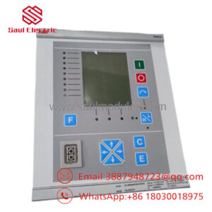
The ABB 3BHE044249R0003, designated as model GDC806C0003, is a high-speed communication and main control interface board deployed within ABB specialized processing platforms, including Unitrol 6000 excitation topologies and AC 800PEC high-speed controllers. It coordinates sub-millisecond process variables and communication bus interfaces to ensure synchronized regulation across demanding power conversion and drive electronics.
Engineers specify the GDC806C0003 for its reliable channel-wise isolation and rigid 250 Veff insulation rating, safeguarding controller backplanes from transient field spikes. This module serves as an exact drop-in component to recover control line stability without requiring modifications to physical rack footprints.
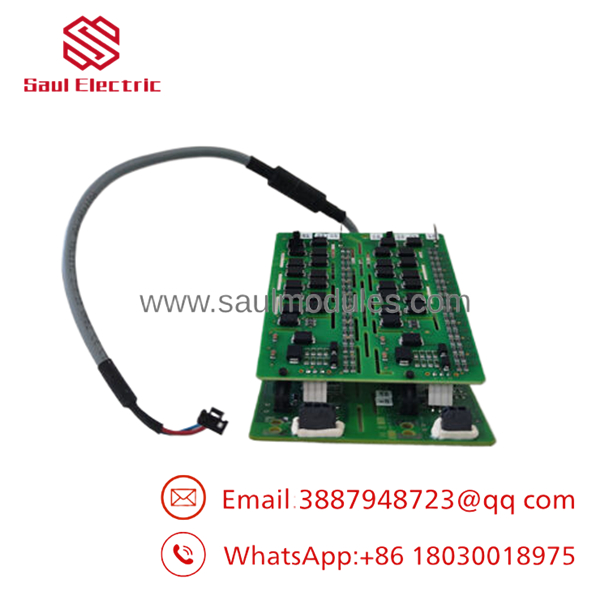
- 3BHE044249R0003 GDC806C0003
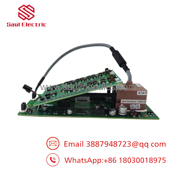
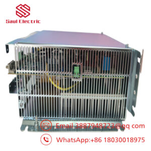
- 3BHE044249R0003 GDC806C0003
Installation & Configuration Guide
1.Pre-Installation Preparation:Estimated time: 10 mins.
Isolate the system. Coordinate with the control room to confirm the plant section or excitation train is completely down. Disconnect and lock out all upstream power supplies feeding the controller enclosure.
⚠️ Stored Energy Hazard: High-power drive and excitation systems contain massive capacitor banks. Wait a minimum of 5 minutes following complete power isolation to permit remaining electrical charges to discharge.
Equip yourself with a grounded ESD wrist strap, a PH1 stubby screwdriver, a Fluke 115 multimeter, and a camera. Connect your service laptop to dump the current runtime parameters, network configurations, and systemic firmware levels before pulling the existing unit.
2.Removing the Old Module:Estimated time: 5 mins.
Securely clip your ESD wrist strap to an unpainted metal surface on the grounding frame. Open the rack swing frame or pull the protective faceplate. Take a high-resolution photograph of any internal optical fiber connections or bus ribbon cables.
Label all lines precisely before manipulation. Unfasten the module retention screws on the board edges. Extract the board smoothly out from the guide slots, pulling parallel to the chassis walls to prevent fracturing the fragile edge-connectors or bending the backplane pin layout. Place the old card into an anti-static bag.
3.Installing the New Module:Estimated time: 10 mins.
Extract the replacement 3BHE044249R0003 GDC806C0003 board directly from its factory ESD packaging inside a protected workspace. Verify that the hardware revision matching code matches your targeted hardware profile.
Configuration Clone: Examine the physical board face and replicate any onboard jumper settings or hardwired micro-DIP switch matrixes using your reference photograph. Incorrect jumper positions can conflict with the bus address structure or reference levels.
Align the board cleanly with the upper and lower slot channels. Slide it inward until the backplane socket engages firmly into place. Secure the mounting hardware and torque all interface connections to OEM specifications.
Self-Checklist:
- [ ] Hardwired jumper arrangements match the decommissioned board exactly.
- [ ] Optical fiber or bus cables are fully locked with zero stress on bend radii.
- [ ] Retaining fasteners are snugged to ground the board frame properly.
4.Power-On & Testing:Estimated time: 15 mins.
Execute a point-to-point resistance check on the auxiliary power supply rails to ensure zero short-circuits remain on the interface line. Apply system power to the processor section only; isolate active field regulators.
Monitor the bootup diagnostic LEDs closely. A healthy initialization displays a solid green run status indicator. Interrogate the module via your programming console to confirm the device address responds on the inner data bus. If the board parameters register normally, run low-level loop tests on peripheral communications prior to reconnecting live operational logic.
⚠️ Troubleshooting Note: If an active fault light illuminates immediately after power-up, cross-reference the system log file to identify any firmware version discrepancies between the main controller application and the board.
Frequently Asked Questions (FAQ)
A: No, this board does not support live insertions or extraction. Swapping the board while the backplane is energized risks causing internal bus data corruption, processor resets, or component failure due to unexpected power-up logic loops. Always confirm power is isolated before working on the system.
Q: Why is matching the exact suffix on the 3BHE044249 board crucial during a replacement?
A: ABB utilizes varying hardware revisions (such as R0003 versus R4002 or R4003) across different build years and application systems like the AC 800PEC or Unitrol 6000. Suffix changes often indicate modifications in physical component footprints, component tolerances, or onboard FPGA baseline coding. Installing an incorrect variant can trigger a severe bus mismatch or peripheral detection fault.
Q: This component appears hard to source from the OEM. What is your warranty and condition policy?
A: Because these systems are frequently used in legacy lines, standard factory lead times can be excessive. We provide these units as New Original Surplus (New Surplus), meaning they are clean, un-fielded spares acquired from plant upgrades or surplus reserve. We back every component with an independent 1-year warranty to guarantee reliable performance under field conditions.
Q: Will installing this board overwrite or delete the plant operating application files?
A: No, it will not. The acts as a specialized communication and interface module rather than the primary non-volatile program storage memory. The main execution application remains inside the system’s controller CPU. However, you must match the physical configuration settings and verification jumpers exactly to enable the host controller to recognize the card upon boot.
Q: What is the purpose of the conformal coating observed on the surface components of the board?
A: The specialized coating provides critical insulation protection against moisture, conductive particulate dust, and mild chemical contaminants typical in industrial power houses or drive rooms. This ensures long-term electrical reliability and helps prevent stray current leaks across the dense terminal pins and high-speed data traces.

 Start Chat


