





Description
Key Technical Specifications
| Parameter | Specification Value |
| Manufacturer | ABB |
| Model Number | REX521GHHPSH06G |
| Auxiliary Supply Voltage | 100-240 V AC / 110-250 V DC |
| Rated Frequency (f_n) | 50 Hz / 60 Hz configurable |
| Phase Current Inputs | 3 Channels, 5 A nominal |
| Earth-Fault Current Input | 1 Channel, 1 A / 5 A nominal |
| Digital Inputs / Outputs | 9 Binary Inputs / 4 Signal Outputs, 2 Power Outputs |
| Communication Interface | RS-480 / Wire Serial or Fiber Optic Option |
| Supported Protocols | Modbus RTU, SPA-bus, IEC 60870-5-103 |
| Enclosure Rating | IP54 (Front panel flush mounted) |
| Operating Temperature | −10 to +55 °C |
Product Introduction & Supply Chain Strategy
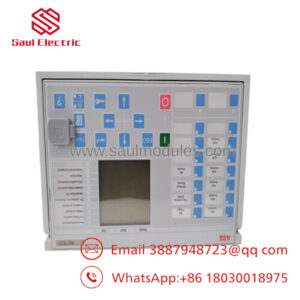
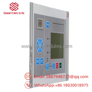
The ABB REX521GHHPSH06G is a dedicated feeder protection relay designed for protection, control, measurement, and supervision in medium-voltage networks and industrial distribution sub-stations. This multi-function unit handles three-phase overcurrent protection, non-directional earth-fault identification, and auto-reclosing functionality, feeding real-time telemetry back to central SCADA systems.
From a strategic supply chain perspective, sourcing this module as New Surplus is a necessary insurance policy against catastrophic plant downtime. Because ABB has moved this series into the obsolete lifecycle phase, relying on the secondary market for refurbished units introduces severe risk. This New Surplus module provides a 100% predictable 10-to-15-year operational lifespan, protecting your Total Cost of Ownership (TCO) and eliminating the lead time variability associated with factory upgrades or unstable, second-hand components.

- REX521GHHPSH06G
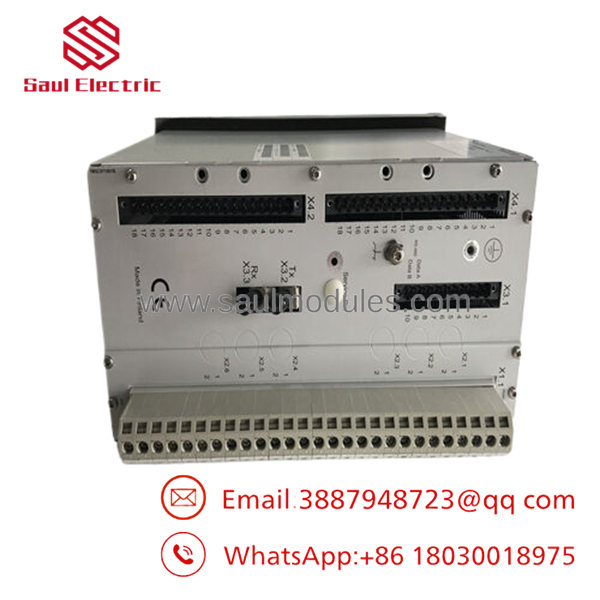
- REX521GHHPSH06G
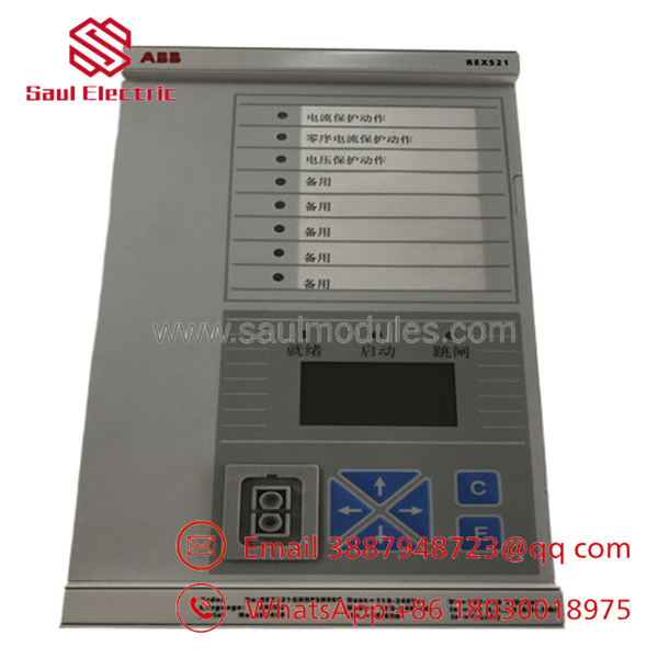
- REX521GHHPSH06G
Installation & Configuration Guide
Stage 1: Pre-Installation (Prep & Safety)
- Isolate Power: Execute lock-out/tag-out (LOTO) protocols on the auxiliary power supply feeding the protection panel.
- Short CT Circuits: Ensure all Current Transformer (CT) secondary circuits are securely shorted before disconnecting the old unit. Opening a live CT circuit creates lethal high-voltage potentials.
- Static Prevention: Ground yourself using a calibrated ESD wrist strap attached to the panel chassis.
- Documentation: Take high-resolution photographs of the rear terminal blocks, noting wire tags, and document the hardware configuration switches on the side of the housing.
Stage 2: Removal
- Unplug the detachable compression screw terminal blocks carefully to prevent mechanical stress on the internal backplane contacts.
- Loosen the flush-mount fixing clamps from the sides of the relay casing.
- Slide the legacy unit forward out of the panel cutout, taking care not to scrape the panel gasket.
Stage 3: Installation (Clone & Seat)
- Verify that the hardware jumpers and DIP switch configuration on the New Surplus REX521GHHPSH06G perfectly match the parameters of the removed unit.
- Slide the new module smoothly into the 19-inch rack or cutout opening until the front bezel seal sits flush against the panel door.
- Hand-tighten the fixing clamps to 1.2 Nm of torque to maintain the IP54 environmental rating.
- Reattach the terminal blocks, ensuring each block seats tightly and locks into position.
Stage 4: Power-On & Testing
- Measure the auxiliary DC voltage rail at the terminals to confirm it falls within the nominal 100-240 V range.
- Energize the auxiliary power circuit. Ensure the green “READY” LED illuminates stable and the “ERROR” LED remains unlit.
- Connect a commissioning PC via the front optical or serial interface to download the verified parameter configuration file (.acf).
- Perform a primary or secondary injection test to verify current measurement loops prior to closing the main breaker.
Firmware/Software Versions & Upgrade Notes
The operates on specific firmware branches determined by its hardware revision code (indicated by the final suffix characters). For typical replacement applications, firmware parity is essential. Mixing older configuration files built in CAP 501 or CAP 505 toolsets with unverified firmware can cause Modbus register shifting or communication timeouts over RS-485 loops.
Critical Notice: Do not attempt to flash legacy REX 521 units with newer protection platform firmware. Firmware mismatches during a physical hardware swap can invalidate protection curve calibration values and render the binary input mappings unresponsive. Always extract the configuration parameters from the old unit and map them to the same or fully backward-compatible firmware baseline.
Frequently Asked Questions (FAQ)
A: Refurbished protection relays pose an unacceptable risk to infrastructure. Components like internal power supply smoothing capacitors and output trip relays degrade over time due to heat and operational cycling. A refurbished unit may look clean on the outside, but its internal components are already aged. If a used relay fails to trip during an overcurrent event, the resulting transformer or switchgear damage can cost hundreds of thousands of dollars. Our New Surplus units have zero operational wear and provide OEM-level reliability.
Q: Are these units actually brand new, or are they just cleaned up?
A: These are 100% brand new, unenergized surplus assets. They originate from canceled projects, facility upgrades, or strategic corporate reserves. They feature factory backplane pins with zero wear, unmarred terminal blocks, and original internal components that have never seen a live electrical load.
Q: Is this specific model number still supported by ABB?
A: No, the REX 521 series has transitioned past its active lifecycle and is considered a legacy/obsolete item by the OEM. Standard factory support is limited, and lead times for direct OEM replacements can extend to months or require an expensive panel retrofit. Sourcing this New Surplus unit allows you to maintain your existing footprint without modifying panel cutouts or rewriting upstream SCADA integration maps.
Q: Can this relay be hot-swapped while the feeder is live?
A: Absolutely not. Never attempt to remove or install a protection relay while the primary circuit breaker is energized. Aside from the risk of arc flash, disconnecting the terminal blocks opens the CT secondary loops, which will destroy the CTs and create an immediate life-safety hazard. Always isolate the panel before servicing.
Q: Does the unit retain its program variables if the auxiliary power drops out?
A: Yes. Configuration parameters, protection settings, and event logs are stored in non-volatile EEPROM memory. The unit does not rely on a continuous volatile power loop or internal batteries to maintain its core protective configuration.
Q: What kind of warranty coverage comes with this surplus unit?
A: While the original factory warranty period from ABB has lapsed, we back this New Surplus module with an independent 1-year operational warranty. This covers all internal board components, firmware stability, and physical I/O functionality under normal operating conditions.

 Start Chat


