





Description
Key Technical Specifications
| Parameter | Value |
| Brand | ABB |
| Part Number | 5SHX2645L0004 |
| ABB Factory ID | 3BHL000389P0104 / 3BHB003154R0101 |
| Semiconductor Technology | Reverse Conducting IGCT (Integrated Gate-Commutated Thyristor) |
| Peak Off-State Voltage (V_{DRM}) | 4500 V |
| Max Cont. Anode Current (I_{TAVM}) | 2645 A (at housing temperature of 85 °C) |
| Max Peak Turn-Off Current (I_{TGQM}) | 7935 A (3x overload capacity) |
| Max Surge Current (I_{TSM}) | 40,000 A (10 ms pulse length) |
| Required Clamping Force | 40 kN (Nominal stack pressure) |
| Gate Control Link | Optical fiber transceiver interface with status feedback loop |
| Cooling Profile | Double-sided water cooling via power stack plates |
| Housing Style | 91 mm hermetic press-pack |
| Net Weight | 2.6 kg |
| Country of Origin | Switzerland / Czech Republic |
Product Introduction
The ABB 5SHX2645L0004, identified by factory catalog number 3BHL000389P0104, is a heavy-duty Reverse Conducting Integrated Gate-Commutated Thyristor (IGCT RC) module engineered for high-power medium-voltage infrastructure. It functions as the core switching element in self-commutated, 3-level voltage source inverters within ABB ACS6000 drive systems and industrial Active Rectifier Units (ARU). By integrating a reverse-conducting GCT wafer with a monolithic freewheeling diode and a low-inductance multi-layer gate driver board, it handles massive current loads up to 4500 V.
Engineers choose this IGCT module for its native snubberless turn-off rating, which completely eliminates the cost, volume, and thermal losses associated with external snubber circuits. Operated via high-speed optical fiber interfaces, it provides maximum electromagnetic immunity and microsecond-level switching coordination in critical metal rolling mills, marine propulsion systems, and static synchronous compensators (STATCOMs).
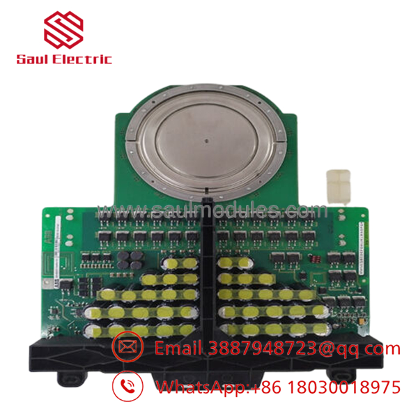
- 5SHX2645L0004
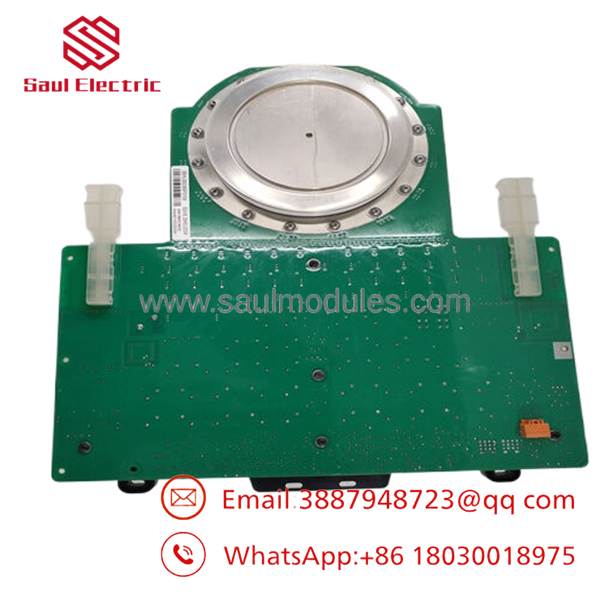
- 5SHX2645L0004
Installation & Configuration Guide
1.Pre-Installation Preparation:Estimated time: 15 mins.
Perform absolute energy isolation. Lock out and tag out the primary medium-voltage vacuum circuit breaker supplying the active rectifier or drive enclosure.
⚠️ Lethal Stored Charge Warning: High-power IGCT inverter stacks are linked to massive DC bus capacitor banks. Wait a minimum of 10 minutes following total input power isolation. Use a certified high-voltage ground probe to verify zero residual voltage across the DC links and phase lines before opening the stack assembly.
Equip your workstation with a calibrated hydraulic or mechanical clamping press (capable of reading 40 kN precisely), a grounded ESD wrist strap, contact cleaning solvent, lint-free towels, fiber optic inspection scope, and a smartphone.
2.Extracting the Failed IGCT Module:Estimated time: 20 mins.
Attach your grounded ESD wrist strap to the chassis frame. Carefully label and disconnect the 24 V auxiliary power harness from the integrated gate driver housing. Disconnect the optical fiber send and receive cables—do not bend the fibers past a 30 mm radius. Cap the fiber ends immediately to protect against airborne grease or dust contamination.
Slowly decompress the power stack hydraulic or mechanical tension mechanism. Note the positioning and compression settings on the gauge. Carefully slide the 2.6 kg press-pack module sideways out from between the water-cooled chill plates, ensuring you do not gouge the bright nickel plating on the heat sink surfaces.
3.Installing and Clamping the New Module:Estimated time: 20 mins.
Unpack the new 5SHX2645L0004 module within a clean, ESD-protected zone. Clean the anode and cathode pole faces of the press-pack, along with the heat sink surfaces, using a lint-free cloth moistened with contact solvent. Apply an ultra-thin layer of high-conductivity thermal compound to the pole faces if directed by the specific drive maintenance manual.
Slide the module into position between the chill plates. Ensure the gate driver housing orientation allows stress-free access for the wiring harness and optical fiber paths.
Clamping Execution (Critical): Gradually apply force using the stack tensioning rig. You must reach exactly 40 kN of uniform pressure. Insufficient clamping force results in excessive electrical and thermal contact resistance, causing the silicon junction to overheat and short out immediately under load. Over-tightening will fracture the internal silicon wafer.
Self-Checklist:
- [ ] Clamping mechanism indicates a steady nominal force of 40 kN.
- [ ] Optical fibers are free from kinks, clean, and securely clicked into their transceivers.
- [ ] Gate driver auxiliary connector is completely seated and locked.
4.Power-On Diagnostic and Loop Testing:Estimated time: 15 mins.
Ensure the cooling water loop is repressurized and check for any leaks around the stack plates. Apply the low-voltage auxiliary power (typically 24 V DC) to the drive control logic first, keeping the medium-voltage main line completely isolated.
Verify the gate unit status feedback loop via the drive’s diagnostic software terminal. Check that the board’s internal optical transmitter communicates healthy status indicators back to the central processor with zero loop errors. Run a low-frequency firing test sequence if supported by the firmware. Once local gating diagnostics pass, seal the drive doors, clear the work area, and safely re-energize the medium-voltage main bus.
Frequently Asked Questions (FAQ)
Q: Can I replace a 5SHX2645L0004 module without a hydraulic clamping rig?
A: No, this is physically impossible and highly dangerous. Press-pack semiconductors rely entirely on external mechanical force to create internal electrical and thermal contact across the silicon joints. Without a specialized, calibrated tensioning rig to apply exactly 40 kN of force, the module will suffer localized arcing and thermal destruction within milliseconds of power application. Never attempt to tighten stack bolts from memory or with a standard wrench.
Q: What is the main structural difference between this module and standard GTO thyristors?
A: Standard Gate Turn-Off (GTO) thyristors require massive, high-loss external snubber circuits (composed of large capacitors and resistors) to limit the rate of voltage rise (dv/dt) during turn-off transitions. The 5SHX2645L0004 features an integrated multi-layer gate driver card that changes the turn-off mechanism, switching the device from a thyristor state to a transistor state in micro-seconds. This rapid execution permits snubberless operation, reducing overall system footprints and internal heat losses.
Q: Why does the 5SHX2645L0004 utilize optical fiber lines for gate signals?
A: Because this module operates in high-voltage environments up to 4500 V alongside rapid, high-current switching cycles, the electrical noise (EMI/RFI) inside the cabinet is severe. Standard copper control lines would pick up inductive interference, leading to false gating signals or destructive cross-conduction. Optical fiber lines provide absolute galvanic isolation between the low-voltage control processors and the high-power medium-voltage semiconductors, ensuring immune, deterministic firing signals.
Q: Is this module suitable for air-cooled drive installations?
A: While the device housing itself is a hermetic press-pack that can technically be adapted to heavy-duty air-cooled heat sinks, the 5SHX2645L0004 configuration in ACS6000 topologies is heavily optimized for double-sided water cooling stacks. Operating this module at its full continuous current rating of 2645 A under standard air cooling alone will typically cause the internal silicon junction temperature to exceed its 125 °C safety ceiling, triggering a thermal trip or immediate semiconductor breakdown.
Q: Why does your pricing for this high-voltage IGCT module vary from direct OEM factory quotes?
A: We procure these high-power modules as New Original Surplus (New Surplus) from cancelled system builds, spare parts distribution networks, and facility reserves. Because we manage these directly outside the extended OEM project-quoting structures, we can provide immediate dispatch and competitive pricing to help plants avoid extended forced downtime during critical drive failures. Every unit is brand-new, un-fielded stock covered by a 1-year warranty.

 Start Chat


