





Description
Key Technical Specifications
| Parameter | Specification Value |
|---|---|
| Protocol Compatibility | Advant Fieldbus 100 (AF100) |
| Hardware Compatibility | System 800xA / Compact Product Suite AC 800M PM8xx CPUs |
| Network Redundancy | Dual channels supported (Line A and Line B monitoring paths) |
| Data Transmission Rate | 250 kbps or 1.25 Mbps matching AF100 standard baselines |
| Current Draw (24 V DC) | Maximum 140 mA from the backplane assembly |
| Power Dissipation | Typical 3.4 W inside active cabinet layouts |
| Connection Interface | 2 x 9-pin D-sub female ports on front edge |
| Isolation Barrier | Galvanic isolation rated up to 500 V AC |
| Module Width | Single width factor slot layout inside TP830 baseplate units |
| Front Status Indicators | LED cluster: Run (Green), Fault (Red), Transmit/Receive Activity |
| Operating Temperature | +5 to +55 °C (+41 to +131 °F) ambient cabinet air |
Product Introduction
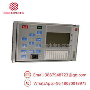
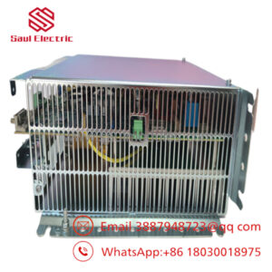
The ABB CI522AK04 (3BSE018451R1) is a specialized communication interface kit that links an AC 800M controller stack to a high-speed Advant Fieldbus 100 (AF100) network infrastructure. This hardware solution allows newer System 800xA controllers to communicate directly with legacy installations, sharing deterministic process variables and control block matrices with older Advant OCS systems, AC 410/450 controllers, or S100/S600 distributed I/O stations.
Equipped with dual 9-pin D-sub physical connections, the CI522AK04 supports line-redundant network paths to protect your plant from sudden media cuts or noisy industrial environments. It plugs natively into a matching TP830 baseplate carrier system adjacent to the primary processing unit. This layout avoids taxing the core CPU overhead while maintaining stable, synchronized cyclic data transfers across your enterprise automation layers.
Installation & Configuration Guide
Stage 1: Pre-Installation Preparation (Estimated Time: 15 minutes)
- ⚠️ Safety First: Modifying active plant network nodes can disrupt deterministic messaging arrays, causing remote I/O nodes or partner controllers to trigger emergency safety stops. Switch associated critical process interlocks to a safe state inside the engineering workspace before pulling any communication links.
- Tools Required: Grounded anti-static (ESD) wrist strap, small flat-blade terminal screwdriver, and a configuration laptop equipped with Control Builder M / 800xA Engineering software.
- Data Backup: Open your active project within Control Builder M. Navigate down the hardware tree topology, locate the specific CI522 instance, and archive all associated fieldbus parameters, including the AF100 station address, cluster settings, and configured cyclic data datasets.
Stage 2: Removing the Old Module (Estimated Time: 5 minutes)
- Affix your grounded ESD wrist strap to a verified metal grounding point inside the enclosure.
- Label and unscrew the dual 9-pin D-sub communication connectors attached to the module faceplate. Slide the line plugs away carefully.
- Loosen the upper and lower panel retention locking screws built into the plastic module shell.
- Pull the module straight forward out from its slot position on the TP830 baseplate.
- ⚠️ Note: Pull smoothly along the guide grooves. Lateral twisting forces can fracture the delicate backplane multi-pin matrix array. Put the removed unit inside an ESD safety bag immediately.
Stage 3: Installing the New Module (Estimated Time: 10 minutes)
- Keep the new surplus CI522AK04 inside its protective packaging until the mounting lane is clean and fully visible.
- Slide the replacement module card straight into the designated baseplate track lane, ensuring its rear pins mate evenly with the backplane receptor socket.
- Push the housing home firmly until you hear the retention clips snap into position, then secure the top and bottom screws.
- Align the labeled 9-pin D-sub connectors for Line A and Line B, push them onto the front ports, and tighten their retaining screws.
Stage 4: Power-On & Testing (Estimated Time: 20 minutes)
- Restore or cycle local power to the AC 800M controller chassis baseplate layout.
- Observe the front panel diagnostic display: The “Run” LED must stabilize into a solid green state, while the “Fault” indicator should extinguish after completing initialization.
- From your engineering platform console, execute a hardware check to confirm the new module is recognized under its configured station address.
- Perform an application download to synchronize the new card firmware tracking with the main CPU engine.
- Monitor your live database variables to verify that cyclical communications between the AC 800M and the remote AF100 nodes resume normal operation without frame errors.
- ⚠️ Troubleshooting Note: If the “Fault” LED blinks red continuously after download, open the Control Builder diagnostic viewer. The most common culprit is a mismatch between the hardware station address assigned in the software tree and the physical properties defined for that slot location.
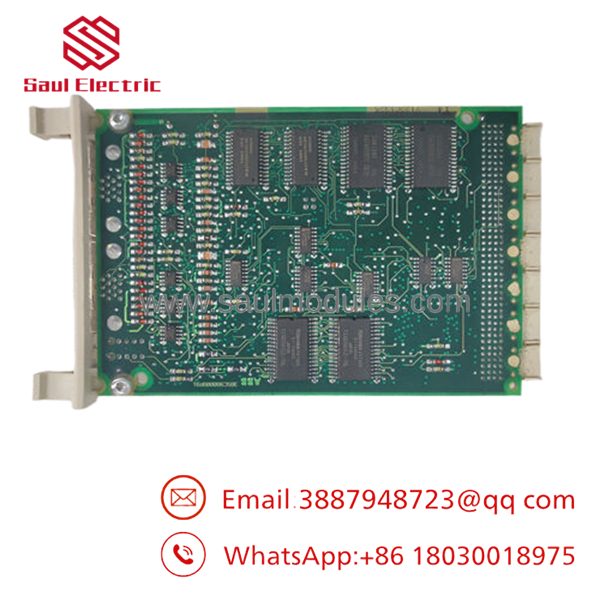
- CI522AK04 3BSE018451R1
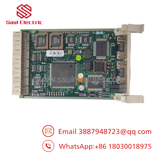
- CI522AK04 3BSE018451R1
Frequently Asked Questions (FAQ)
Can the CI522AK04 card be hot-swapped while the plant is operating?
Yes, the AC 800M platform supporting the CI522 interface kit allows hot-swapping under power. If you are operating a redundant system with a dual-module pairing, pulling a single faulted card will trigger a quiet transfer to the tracking partner without dropping network communications. However, if you are running an un-redundant network setup, pulling the module will drop all communication to that specific AF100 loop instantly.
What is the exact difference between the CI522 module and the kit?
The base number “CI522” refers exclusively to the internal physical communication electronic board asset itself. The “” part number defines a comprehensive commercial system hardware kit, which includes the properly flashed communication module, matching terminal connectors, and required mounting accessories to perform a complete installation in a standard industrial cabinet environment.
Does this module require an external GSD file or third-party drivers?
No, the protocol is an internal, proprietary network architecture developed by ABB. The configuration parameters, memory block configurations, and driving stack layers are natively compiled inside the standard ABB Control Builder M software utility. You do not need external GSD or EDS definition profiles to get the node up and running.
What causes an intermittent “Line Error” indication on this module’s diagnostic log?
Intermittent errors are typically caused by physical bus infrastructure problems. Check for incorrect termination resistor values at the physical end boundaries of the trunk line. Other common issues include poorly crimped shield bonds on the coaxial or twisted-pair network cable lines, or running your communication lines too close to high-voltage motor drive lines.
Are these legacy cards tested before shipping from your surplus stock?
Yes, absolutely. Our quality control procedure dictates that every surplus or refurbished kit passes through an authentic inspection and physical test configuration rack before it is packed. We slot the module into a running AC 800M baseplate, verify power-on self-diagnostics, and initiate active cyclic data exchanges across a real bus loop to ensure the card performs reliably in production.

 Start Chat


