





Description
- Key Technical Specifications
- Model: CS31ICSO16N1
- Brand: ABB
- Product family: Procontic CS31
- Module type: Digital output module
- Output channels: 16
- Output rating: 24 V DC
- System interface: CS31 system bus
- Use case: Remote discrete output expansion
- Mounting: Panel/rack installation, site dependent
- Compatibility note: Verify base unit and bus master version before installation
- Condition: New Original / New Surplus
- Availability note: Limited stock expected on legacy CS31 parts
- Product Introduction
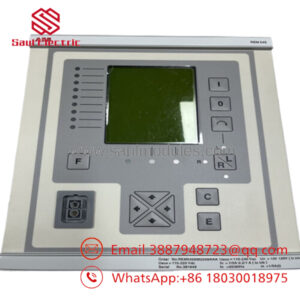
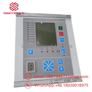
ABB CS31ICSO16N1 is a 16-channel digital output module for the ABB Procontic CS31 decentralized automation system. It is used to switch field loads from a CS31-controlled rack or remote I/O station.
This module is chosen for legacy CS31 installations that need output expansion without changing the controller architecture. In field replacements, the critical points are bus compatibility, wiring verification, and matching the existing addressing scheme.
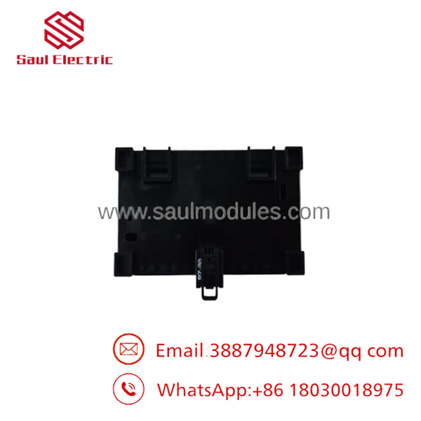
- CS31ICSO16N1
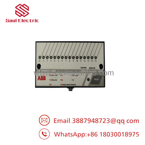
- CS31ICSO16N1
- Installation & Configuration Guide
Stage 1: Pre-Installation Preparation
⚠️ Safety first: Notify operations, verify the process is in a safe state, lock out/tag out power, and wait at least 5 minutes for capacitor discharge.
Tools required: ESD strap, PH1 screwdriver, multimeter, wire labels, smartphone for photos.
Data backup: Record the running logic, note bus/master addresses, photograph DIP switches, and capture terminal wiring before removal.
Estimated time: 5-10 minutes.
Stage 2: Removing the Old Module
- Remove the front cover or bezel.
- Label and disconnect all wiring. Do not force terminals.
- Release the DIN rail or rack locking tabs and pull the module straight out to protect the backplane pins.
- Inspect the backplane and connector area for bent pins, dust, or heat damage.
⚠️ Keep the old module until the replacement is running normally.
Estimated time: 5-8 minutes.
Stage 3: Installing the New Module
- Put on ESD protection and verify the exact model number matches.
- Clone the configuration from the photo. Copy any DIP switch or jumper settings exactly, especially node address and termination.
- Insert the module into the rack until it seats fully and locks.
- Reconnect the wiring with the correct torque and terminal order.
Self-checklist: [] DIPs match, [] wiring secured, [] tabs locked.
Estimated time: 8-10 minutes.
Stage 4: Power-On & Testing
- Use a multimeter to check for shorts on the 24 V rail before energizing.
- Power up the rack only, not the field loads.
- Watch the LEDs. Green RUN is normal; red ERR needs investigation.
- Connect the programming tool, confirm the bus address and firmware version, and restore the backup logic if required.
- Run a dry test on the outputs before returning the process to service.
⚠️ Troubleshooting note: If ERR stays solid red, suspect a firmware or address mismatch first. If there is no communication, check bus settings and the master-side configuration.
Estimated time: 10-15 minutes.
- Frequently Asked Questions
Q: Can I hot-swap this module under power?
No. Treat it as a power-down replacement unless the site manual explicitly says otherwise. Pulling it live can damage the module or the backplane.
Q: Is this model obsolete?
Yes, this is a legacy part, so stock is usually limited. That is normal for this platform, and condition should be verified before purchase.
Q: Will my programming stay intact when I replace it?
The program usually lives in the controller or master, not in the output module itself. Still, back up the full system before touching hardware.
Q: What is the direct replacement if this exact part is unavailable?
That depends on the installed base, bus master, load type, and wiring style. I would not guess a substitute without checking the exact site hardware.
Q: Why is the price lower than OEM list pricing?
Legacy surplus stock often sells below factory list price. The tradeoff is lead time, stock variability, and the need to verify condition and traceability.
Q: What condition should I expect?
For this type of part, the common offers are New Original, New Surplus, or Refurbished. For procurement, insist on a clear condition statement and test record.
Q: What usually causes replacement failure?
The three usual causes are wrong addressing, mismatched wiring, and missed bus termination. Those are the mistakes that waste hours in the field.

 Start Chat


