





Description
Product Introduction & Engineering Value
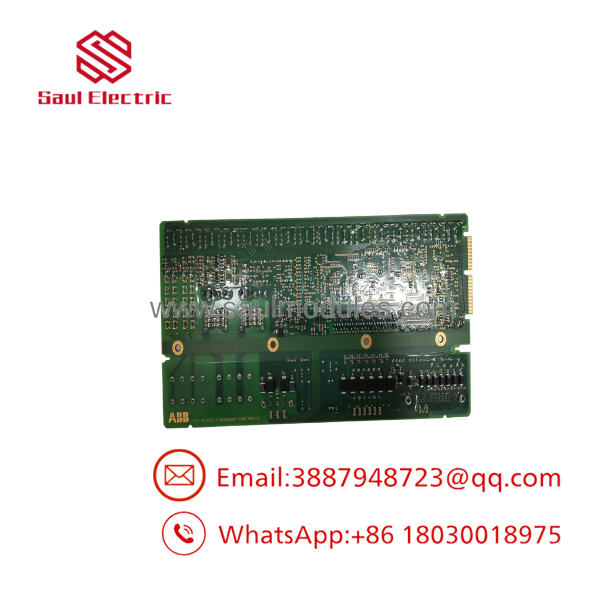
In high-power medium voltage (MV) drive topologies, optical isolation between high-voltage inverter stages and sensitive low-voltage control hardware isn’t optional—it’s safety-critical. The ABB GFD212A (3BHE020356R0101) serves as the primary signal distribution bridge, interfacing main processor boards (such as the GCC series) with localized power gate drive modules.
By routing PWM firing triggers across fiber-optic channels and gathering real-time feedback on cell faults, cabinet door interlocks, and current monitoring loops, the GFD212A prevents severe high-voltage noise transients from bleeding into the control bus. Swapping a suspect GFD212A card restores full pulse integrity and diagnostic feedback across the converter stack.
Technical Specifications
- Operating Input Voltage: 24 V DC (±15%) via backplane rail, low-power design (<6 W)
- Optical Channels: Multi-channel fiber optic transceiver array for PWM trigger distribution and fault feedback loops
- Isolation Withstand Rating: ≥ 5 kV AC high/low voltage galvanic barrier
- Communication Interfaces: High-speed backplane bus for main controller link; onboard CAN 2.0 supporting Modbus/Profinet expansion
- Terminal I/O Integration: External pluggable terminal blocks for cabinet temperature, fan status, door interlocks, and charging contactor feedback
- Analog Sampling: Dual-channel high-precision current acquisition for output closed-loop protection
- Operating Temperature: 0°C to +60°C (32°F to 140°F) standard industrial enclosure range
- Form Factor: Compact slot-card layout with reinforced front optical connector housings
Field Application & The “Trench” Experience
The Trench Story
A cement plant running a large raw mill on an ABB MV drive experienced intermittent “Cell Gate Fault” trips during peak production hours. Scope testing showed that main control signals were sending properly, but firing feedback on Phase B was dropping out sporadically. Inspecting the GFD212A interface card revealed that one of the fiber optic receiver ports had suffered physical strain, loosening its solder connection to the PCB.
The instrument technician isolated the power cabinet, pulled the optical ribbon bundles using a labeled strain-relief kit, and swapped the card out with a pre-tested GFD212A spare. After cleaning the fiber tips and reseating the optical connections, the drive went through a full pre-charge sequence without faulting, getting the mill back to 100% capacity in under 45 minutes.
Specific Niche Applications
- Cement Mill & Kiln MV Drive Cabinets: Processing high-voltage isolation signals and local enclosure thermal interlocks.
- Power Plant Induced Draft (ID) Fan Drives: Managing fiber-optic PWM pulse distribution and contactor feedback loops.
- Gas Compression Station Variable Frequency Drives: Interfacing control logic to power phase blocks in high-vibration environments.
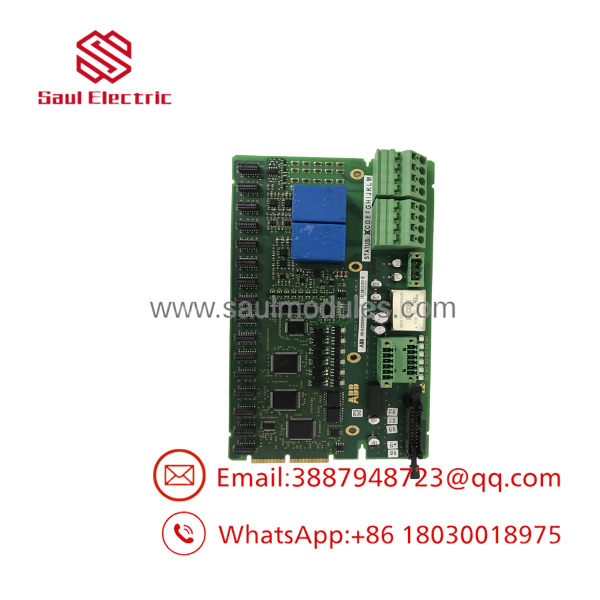
- GFD212A
Transparency SOP: QA & Testing
- Visual & Structural Inspection: Inspect board surfaces under optical magnification for thermal stress, fractured fiber-optic transceiver housings, and pin header integrity.
- Backplane Logic Verification: Mount the on a test rack to verify that internal 24V power distribution stays within the <6W power consumption window.
- Fiber Channel Loopback Test: Inject high-frequency optical signals into every transceiver channel. Measure output pulse delay and waveform symmetry on a high-speed oscilloscope.
- Peripheral Terminal I/O Check: Toggle digital inputs (door interlocks, contactors) and apply calibrated voltage signals to test analog current-sensing channels.
- Burn-In Chamber Test: Subject the card to a 12-hour thermal stress cycle at 55°C to rule out heat-related optocoupler degradation.
The Veteran’s Tech Trap Guide
- ⚠️ Mind the Fiber Optic Bend Radius: Fiber patch cables connected to the front of the can easily be pinched when closing cabinet doors. Always maintain a minimum 30 mm bend radius to prevent internal glass fiber micro-fractures that trigger ghost feedback errors.
- PRO TIP: Keep Optical Connectors Dust-Free. Whenever disconnecting fiber lines from the during maintenance, immediately cap both the board ports and cable ends. A single speck of cement or coal dust inside the receiver optic will attenuate the signal enough to cause pulse-dropping faults.
- ⚠️ Label Terminal Blocks Before Removal: The hosts both optical connections and green pluggable wiring terminals for cabinet monitoring. Mixing up door interlock or contactor feedback wiring during a rush card swap can lock out the main controller’s pre-charge sequence.
Dynamic FAQ
Q: Does the require firmware loading when replacing a faulty card?
A: No. The operates as an interface and signal transport board. Drive parameters and system control firmware reside in the main CPU board (e.g., GCC series), making the a direct hardware swap.
Q: What is the main cause of optical channel failures on this board?
A: Thermal aging of the onboard LED transmitters and dirt contamination on optical ports are the primary culprits. Environmental heat gradually degrades transceiver output power over years of continuous operation.
Q: Are these modules fully tested before shipment?
A: Yes. Every card (3BHE020356R0101) undergoes visual verification, optical transceiver testing, I/O channel validation, and thermal burn-in before entering inventory.
Q: What warranty is provided with your surplus inventory?
A: We back all new surplus and fully reconditioned original ABB boards with a comprehensive 1-year replacement warranty.

 Start Chat


