





Description
Key Technical Specifications
| Parameter | Value |
| Part Number (ID) | 64669303 |
| Model Designation | NAIO-03F |
| Input Voltage | 24 V DC (\pm 10\%) |
| Channels | Multi-channel analog inputs and outputs (isolated) |
| Communication Interface | Fiber optic link (DDCS protocol) |
| Compatibility | ABB ACS800 series frequency converters / industrial drives |
| Net Weight | 0.38 kg (0.60 lbs) |
| Operating Temperature | 0 to +50 °C |
| Storage Temperature | −40 to +70 °C |
| Country of Origin | Finland (FI) |
Product Introduction
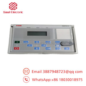
The ABB NAIO-03F (64669303) is an analog I/O extension module engineered specifically for the ACS800 series of industrial adjustable speed drives. It provides additional highly precise analog interfaces required for complex process control setups, allowing your drive to interface directly with external sensors, actuators, and instrumentation. By transmitting data over dedicated fiber optic cables using the DDCS protocol, the module isolates control signals from heavy electromagnetic interference typical in motor control environments.
Plant operators select this specific hardware kit when standard drive control board I/O is exhausted or when high-voltage physical separation is required for signal integrity. The kit includes the expansion board alongside the necessary fiber optic cabling components, securing a high-speed, noise-immune data handshake with the drive’s main control unit. It mounts directly into the option slots or an external rack setup depending on the drive’s frame size.
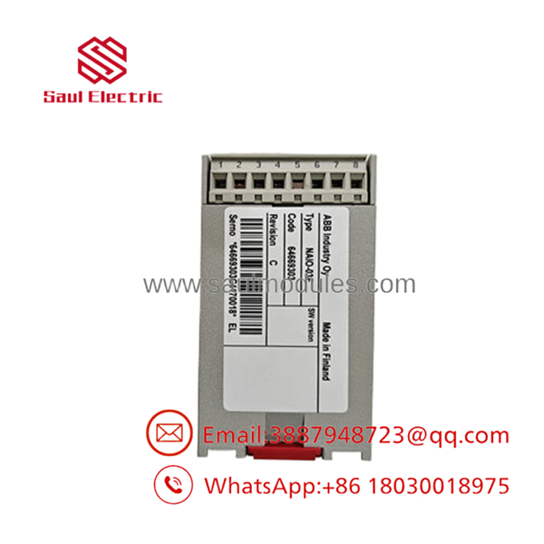
- NAIO-03F 64669303
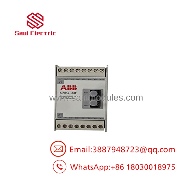
- NAIO-03F 64669303
Troubleshooting Quick Reference
| Symptom | Possible Cause | Relevance to this Part | Quick Check Method | Recommendation |
| No status LEDs illuminated | Loss of 24 V DC logic power | ❌ Low | Measure voltage across the 24 V DC input terminals using a Fluke 115 multimeter. | Verify external power supply fuses and terminal block wiring before pulling the board. |
| Drive faults with ‘CHO COMM LOSS’ or similar DDCS error | Bad fiber optic connection or damaged optical transceiver | ✅ High | Check fiber cable routing for sharp bends. Inspect the optical tips for dust or fracture. Ensure TX and RX channels are not swapped. | Clean fiber ends with an isopropyl wipe or replace the fiber optic link assembly. If the transceiver is dead, replace the board. |
| Analog reading frozen or drifting rapidly | Signal loop ground fault or channel degradation | High | Disconnect field wiring. Inject a known 4–20 mA signal directly into the module terminals using a process calibrator. | If calibration values match the drive parameters, troubleshoot field wiring/transmitters. If readings mismatch, replace the NAIO-03F module. |
| Drive does not recognize the expansion card | Node ID conflict or incorrect slot placement | Medium | Check the positions of the hardware DIP switches on the module. Cross-reference with your drive parameter settings. | Match the binary configuration of the old unit exactly. Power cycle the drive to force hardware re-enumeration. |
[!NOTE]
If diagnostic steps fail to resolve the issue, copy your exact drive fault logger codes, take clear high-resolution photos of the physical jumper configurations, and forward them to our technical support team for detailed analysis.
Frequently Asked Questions (FAQ)
Can I hot-swap the NAIO-03F module while the ACS800 drive is energized?
No, it is not hot-swappable. Pulling or inserting this card while the drive is powered can cause an electrical arc across the backplane pins, potentially damaging the drive’s main control board (RMIO) or frying the logic circuits on the . Always isolate the main supply breaker and wait at least 5 minutes for the intermediate DC bus capacitors to discharge to a safe level before opening the enclosure or swapping options.
What is the purpose of the fiber optic cable included in this kit?
The fiber optic link handles data exchange via the DDCS (Distributed Drives Communication System) protocol. Industrial environments are flooded with high-frequency electromagnetic noise generated by the drive’s IGBT switching circuits. Standard copper control cables run the risk of picking up cross-talk or noise, corrupting analog readings. Fiber optics completely eliminate electrical noise susceptibility and provide total galvanic isolation.
Why do I need to look closely at DIP switch settings during installation?
The relies on physical DIP switches on the circuit board to define its node address and communication configuration. If you leave a replacement card on factory default settings, the drive’s control firmware will not find it, resulting in a persistent options communication fault. Take a photo of the original board’s switches before removal and replicate the layout exactly on the replacement card.
What condition are these units in, and how are they verified functional?
We supply both New Surplus (original factory boxes that were never deployed) and fully Refurbished units. Because these modules are discontinued by the manufacturer, our engineering team puts every single piece through a full physical audit and functional test sequence. We inspect the PCB under magnification for trace corrosion, verify power-on self-test operations, and link the card via fiber to an in-house ACS800 test platform to simulate active analog signal inputs and outputs under thermal load.
Is this unit a direct replacement for older NAIO-01 or NAIO-02 models?
Not directly without cross-referencing your drive firmware and wiring configuration. The features design updates and subtle protocol variation handling that requires checking your drive’s firmware compatibility matrix. If you are converting from an older generation, check the pinouts in the drive manual, as shielding arrangements and minor terminal positions might require you to modify your existing panel wire labels.


 Start Chat


