





Description
Key Technical Specifications
| Parameter | Value |
| Full Order Code | HBFEAEAGABCCANC11E |
| Standard Configuration | Configuration E (Directional Earth-Fault + Phase-Voltage Measurements) |
| Application | Medium-voltage utility and industrial feeder protection |
| Auxiliary Power Supply | 48–250 V DC / 100–240 V AC |
| Analog Inputs | 4 CT (Current Transformers) + 3 VT (Voltage Transformers) |
| Binary Inputs/Outputs | 11 Binary Inputs, 10 Binary Outputs (Configuration Dependent) |
| Protocols Supported | IEC 61850, Modbus RTU/TCP, DNP3, IEC 60870-5-103 |
| Ethernet Port Type | 100Base-TX (RJ45 interface) or 100Base-FX (LC interface) options |
| Mounting Style | Flush panel mount or detached HMI option |
| Protection Functions | 51P, 50P, 67, 51N, 50N, 67N, 27, 59, 81, 50BF |
| Enclosure Rating | IP54 (Front face when panel mounted) |
| Dimensions (H x W x D) | 177 mm x 177 mm x 201 mm (Standard 615 series chassis) |
Product Introduction
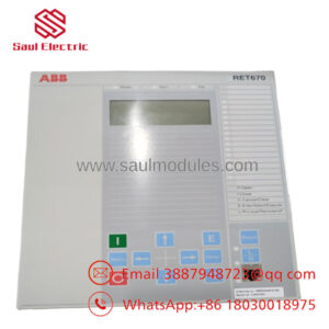
The ABB REF615E_E HBFEAEAGABCCANC11E is a high-capability feeder protection and control relay from ABB’s Relion 615 product family. Engineered to meet strict IEC standards, this Intelligent Electronic Device (IED) provides core protection, measurement, and supervision for overhead lines, underground cable feeders, and busbar networks in utility and industrial distribution substations. Featuring standard configuration “E”, this specific build integrates non-directional and directional overcurrent protection with advanced phase-voltage based measurements, allowing for reliable directional earth-fault isolation in isolated, resistance-earthed, or compensated power grids.
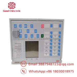
Built with a compact, native withdrawable-unit design, the REF615E_E speeds up physical deployment and maintenance, enabling rapid plug-and-play swaps without altering terminal wiring. The relay utilizes native IEC 61850 protocol mapping to capture the benefits of horizontal GOOSE messaging, reducing hardwired inter-panel connections and lowering communication latency across substation automated frameworks.
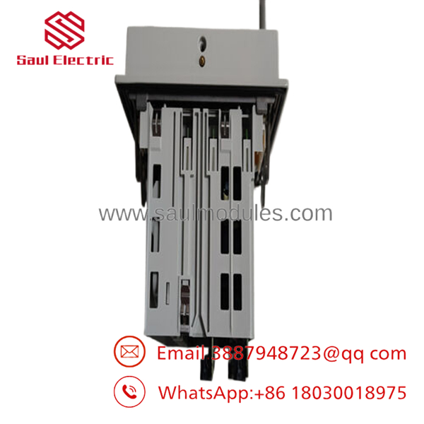
- REF615E_E HBFEAEAGABCCANC11E
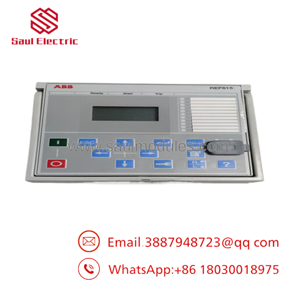
- REF615E_E HBFEAEAGABCCANC11E
Strategic Logic Frameworks
【Core Strategy 1: SOP Quality Transparency】
Handling high-criticality protection relays requires rigorous verification. Because a failure on a feeder protection unit compromises downstream safety and equipment integrity, we pass every surplus and new-surplus REF615 unit through a strict engineering quality protocol before shipment:
- Inbound Inspection & Traceability:
- Source Audit: Every IED is cross-referenced with original ABB lot codes and manifest logs to guarantee genuine OEM lineage.
- Physical Integrity Inspection: We look for housing scratches, terminal strip fractures, or bent grounding clips under localized lighting.
- Hardware Label Verification: The multi-digit order code (HBFEAEAGABCCANC11E) is systematically decoded character-by-character to confirm the accurate matching of functional blocks, hardware revisions, and auxiliary voltage tolerances.
- Live Functional Testing:
- Test Bench Setup: Units are powered up using an OMICRON or Doble secondary injection test set paired with ABB’s PCM600 Protection and Control IED Manager software.
- Power-On Diagnostics: We monitor the internal boot-up sequence, self-supervision (IRF) relay contacts, and the front-panel LCD interface for diagnostic stability.
- Injection Verification: We execute secondary current and voltage injections to confirm calibration on all CT and VT paths.
- Communication Handshake: The RJ45/Fiber Ethernet ports are assigned static IP addresses to verify active communication, ping responsiveness, and firmware configuration access via web UI or PCM600.
- Load Simulation: Every relay undergoes a 24-hour continuous power-on burn-in sequence within an enclosed environmental chamber to ensure internal power supply stability under thermal shifts.
- Electrical Parameter Testing:
- Insulation Resistance Testing: Tested via a Fluke 1587 Megger between independent galvanic circuits (Power Supply, Binary I/O, Analog Inputs) and the chassis earth terminal at 500 V DC, verifying values exceed 20 MΩ.
- Binary I/O Verification: Every physical binary input channel and output contact is pulsed to ensure correct hardware handshakes.
- Firmware & Configuration Verification:
- Firmware Version Logging: Current active software build and application packages are recorded.
- Factory Reset Application: The relay application parameters are wiped to a baseline factory configuration status unless specific customer configurations are requested.
- Final QC & Packaging:
- Engineering Sign-off: Signatures from the primary testing technician and lead quality inspector are affixed to the internal file.
- ESD & Mechanical Shielding: Sealed inside heavy-duty anti-static barrier sheets and protected by custom-cut form-fitting foam within thick corrugated packaging blocks.
Note: Calibrated secondary injection verification data logs and system boot photos for your unique serial number are archived and sent upon request.
【Core Strategy 2: Technical Pitfall & Survival Guide】
Replacing a protection relay requires careful attention to detail. Substation integration problems usually happen because of hidden configuration settings or subtle terminal mismatches. Use these field-proven checks:
- The Order Code Decoupling Trap:
- ❗ The Issue: The designation “REF615” is just the family name. The 18-digit sequence (HBFEAEAGABCCANC11E) contains critical details. Missing one letter means your replacement could have the wrong binary I/O count, different current/voltage input ratios, or incompatible communication hardware.
- Avoidance: Never order a replacement based on the “REF615” stamp alone. Always audit the long string order code stamped on the side plate of the withdrawable sleeve and the plug-in module.
- Field Anecdote: “We had an emergency outage where a plant manager ordered a generic REF615 off an online store. When it arrived, it had the wrong terminal options—4 CTs but no VT inputs—because the order code digits didn’t match. The line stayed dark for another 3 days while we tracked down the exact configuration.”
- CT Shorting Bar Verification:
- ❗ The Issue: Pulling a live protection module without ensuring the case-resident CT shorting bars engage correctly will cause an open-circuit current transformer condition, creating high voltages that can destroy your wiring or cause an arc flash.
- Avoidance: Before sliding the active chassis unit out of its sleeve, verify the mechanical alignment pins are clear and that the shorting mechanism functions smoothly. Never bypass the outer case terminal blocks under load.
- Field Anecdote: “I once saw an operator yank a relay assembly out of a panel with a sticky shorting bar. The CT opened up, and the terminal blocks melted instantly. It’s a major safety hazard—always visually check the bars before pulling the module.”
- Firmware & Parameter Configuration Matrix (PCM600):
- ❗ The Issue: Inserting a replacement unit with an outdated or significantly advanced firmware baseline relative to your companion bay devices can break your IEC 61850 GOOSE network interlocks.
- Avoidance: Extract the application parameters (
.pcmior.cidfile) from your legacy relay prior to replacement using PCM600. Verify the application build configuration block matches the target device before sending the downline configuration.
- Binary Input Wetting Voltage Alignment:
- ❗ The Issue: The binary card input thresholds inside the REF615 are configurable or hardware-specific. If your station control voltage is 48 V DC but the replacement unit is physically hardwired or configured via internal jumpers for a 110 V DC activation threshold, the relay will fail to register digital status changes.
- Avoidance: Double-check the hardware specification and application software settings for threshold values before connecting external field inputs.
Installation & Configuration Guide
Estimated Time to Complete: 45–60 minutes
Target Audience: Substation Technicians / Protection Engineers
Stage 1: Pre-Installation Preparation
- ⚠️ Safety First: Isolate the medium-voltage circuit breaker up-line and down-line. Verify isolating disconnects are physically locked and tagged out according to regional utility regulations.
- CT Isolation: Short-circuit all external current transformer inputs externally at the terminal block before carrying out physical work on the relay sleeve.
- Tools Required: Grounded ESD wrist strap, terminal lug driver, small flat screwdriver for draw-out latches, PC running ABB PCM600 with matching connectivity packages.
- Backup Collection: Connect your engineering workstation to the front optical or RJ45 maintenance port of the active unit and export the existing configuration file (
.pcmiformat).
Stage 2: Removing the Old Module
- Ground yourself using an ESD wrist strap hooked directly to the switchgear metal enclosure.
- Release the relay plug-in module latch mechanics by pivoting the draw-out handles outward.
- Pull the internal chassis unit straight out of the case enclosure. Use stable, parallel guidance to ensure the internal guide tracks don’t bind.
- Set the removed plug-in assembly on an static-safe workspace.
- Inspect the internal case wiring blocks for discoloration, dust accumulation, or loose ring-lug terminal crimps.
Stage 3: Installing the New Module
- Unpack the replacement REF615E_E chassis from its ESD packaging layer.
- Verify that the order code string on the slide-out module exactly mirrors the code on the fixed panel enclosure.
- Slide the replacement unit into the case rail channels, pushing steadily until the latching handles automatically engage and snap into their closed position.
- Secure the secondary manual retention locking pins on the bezel if present.
Stage 4: Power-On & Testing
- Apply auxiliary control power to the relay panel (typically via the station battery bank).
- Boot-Up Monitor: Watch the front LCD screen. The green ‘Ready’ LED should turn solid within 60 seconds. The red ‘Internal Relay Fault’ (IRF) indicator must remain completely dark.
- Attach your configuration PC to the front communications port.
- Open PCM600, establish communication with the target unit, and read out the device properties to verify firmware parity.
- Upload your saved application file (
.pcmi) containing your custom protection parameters and logic curves directly into the new unit. - Run a primary injection or secondary injection test sequence across all phases to check that the relay correctly reads secondary current and voltage values before re-energizing the main circuit breaker.
Frequently Asked Questions (FAQ)
What exactly does the standard configuration “E” specify inside this relay?
Standard Configuration E is tailored for directional overcurrent and directional earth-fault protection setups that require phase-voltage measurements. Unlike basic non-directional options (such as configurations A or C), the E-variant includes internal analog voltage inputs (VTs). This lets the device track phase angle relationships between currents and voltages, making it ideal for systems with isolated, resistance-earthed, or resonant-grounded neutral networks where directional sensitivity is critical for isolating faults.
Can I insert a REF615 plug-in unit into an existing case sleeve without altering any wiring?
Yes, that is a core design benefit of ABB’s Relion 615 series. The draw-out construction allows you to pull the active processor and measurement electronics package forward out of the frame without touching the field wiring landed on the rear ring-lug terminals. As long as the replacement unit’s order code matches the case code exactly, it is a direct mechanical and electrical swap.
What happens if the internal relay fault (IRF) LED lights up red during power-on?
A steady red IRF LED indicates that the internal self-supervision system has detected a critical hardware or software problem during the boot routine or runtime diagnostics. This can point to an internal power supply issue, analog board calibration loss, or corrupted flash memory. If this happens, connect via to read the error log files for specific diagnostic codes. Do not put the relay into active service while the IRF flag is active.
How do I verify that the binary input voltages match my station control battery?
The hardware input threshold configuration can vary depending on the specific build option selected within the order code matrix. You can check the current thresholds via the front HMI menu or through under the hardware settings tab. If the thresholds are adjustable, make sure they are set to match your physical station batteries (e.g., set the threshold to roughly 60–70% of nominal voltage) to avoid false triggers or missing input signals.
Why is it critical to get the exact “” code instead of just any ?
The exact code defines the hardware configuration of the relay. Each position specifies critical components: the auxiliary power supply rating, the specific communication cards (such as dual fiber optic vs. single RJ45 ports), the number of binary inputs and outputs, and the installed protection algorithms. Using an incorrect code can cause physical connection mismatches or missing logic blocks that will break your control schemes and trip logic.

 Start Chat


