





Description
Key Technical Specifications
| Parameter | Value |
| Model Designation | NDBU-95C |
| Product ID (Part Number) | 64008366 (also referenced as 3AFE64008366) |
| Core Functionality | 9-channel optical branching/distribution unit (1 Master, 8 Followers) |
| Optical Link Speed | 1 to 10 MBd |
| Fiber Optic Media Compatibility | Plastic Optical Fiber (POF) or Hard Clad Silica (HCS) |
| Input Power Supply Voltage | 24 V DC (\pm10%) |
| Current Consumption | Max 150 mA (excluding external load/switch configurations) |
| Protective Coating | Conformal Coated (NDBU-95C version) for harsh environment resilience |
| Physical Dimensions | 264 mm (H) x 94 mm (W) x 41 mm (D) |
| Net Weight | 0.73 kg (1.6 lbs) |
| Isolation | Galvanic isolation between power terminal and logic circuitry |
| Country of Origin | Finland / Sweden |
Product Introduction
The ABB NDBU-95C (64008366) is a high-performance 9-channel DDCS (Distributed Drives Communication System) branching unit. Engineered primarily for ACS800 and DCS800 multi-drive topologies, it serves as a central optical divider or hub, allowing a master controller (such as an AC 800M or a primary drive control board) to coordinate with up to eight downstream follower drives or peripheral devices using noise-immune fiber optics.
Unlike standard networking hardware, the NDBU-95C utilizes advanced optical transmitter and receiver components rated for 10 MBd transmission speeds. Crucially, the “C” suffix indicates that the printed circuit board is factory conformal coated, protecting sensitive traces from conductive dust, moisture, and corrosive industrial atmospheres. This makes it a critical part of high-uptime topologies in paper mills, steel lines, and marine propulsion plants.
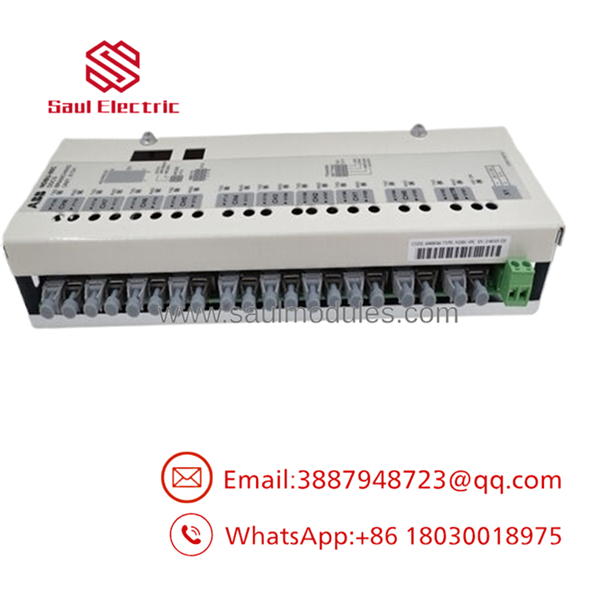
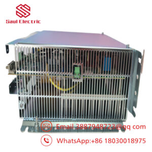
- NDBU-95C 64008366
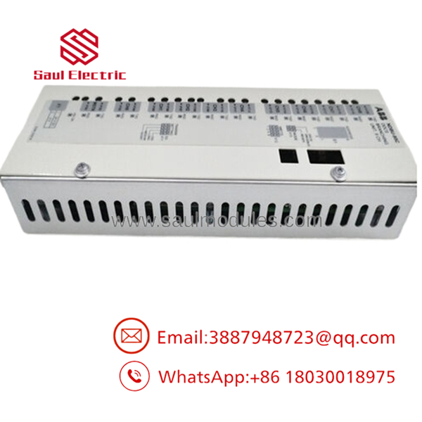
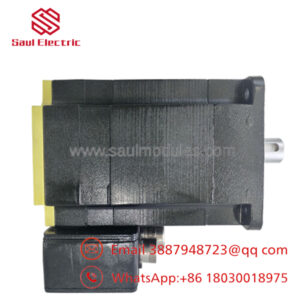
- NDBU-95C 64008366
Installation & Configuration Guide
Stage 1: Pre-Installation Preparation
- Estimated Time: 10 minutes
- ⚠️ Safety First: Isolate the main drive panel power supply and verify with a multimeter that the 24 V DC auxiliary rail is completely dead. Lock out and tag out (LOTO) the breaker. If the unit is located inside a drive enclosure, wait at least 5 minutes for the internal DC bus capacitors to discharge.
- Tools Required: Grounded ESD wrist strap, small flathead screwdriver (for DIP switches and power terminals), and a camera (for configuration reference).
- Data Backup: Document the physical node addresses of all connected follower drives on the optical channels (CH1 through CH8) and note down the exact orientation of the DIP switches on the existing board.
Stage 2: Removing the Old Module
- Estimated Time: 5 minutes
- Steps:
- Affix your ESD wrist strap to an unpainted grounded point on the enclosure chassis.
- Unplug the 24 V DC power connector (X1) from the module.
- Carefully disconnect each of the fiber optic pairs (MSTR, CH1–CH8). Label each fiber pairing clearly (e.g., RX/TX for Channel 1) to prevent reversed polarity during reinstallation. Gently handle fiber lines; do not bend them beyond a 50 mm radius.
- Release the DIN-rail retention clips or unscrew the panel-mounting screws, then pull the unit straight off the rail.
Stage 3: Installing the New Module
- Estimated Time: 10 minutes
- Steps:
- Position the new NDBU-95C on an ESD mat.
- Configuration Clone (Critical step): Replicate the configuration jumper and DIP switch settings from your old unit onto the new board.
- Jumper X13 (MODE): Confirm if it is set to standard
DDCS/DriveBus(default pins 1-2 and 3-4) orREGEN(pins 2-4 and 1-3). - Switch S1 (Node Address): If configured in a cascading chain of multiple branching units, set S1 to match the exact physical address of the replaced unit.
- Optical Power (Transmitter Current): Ensure jumpers match your fiber run lengths (Short, Medium, or Long settings) to prevent receiver saturation or signal loss.
- Jumper X13 (MODE): Confirm if it is set to standard
- Snugly snap the unit back onto the DIN rail until you hear the locking tabs engage.
- Clean the optical tips with an approved fiber cleaning tool, then reconnect each pair to its corresponding channel.
- Reinsert the 24 V DC power plug into terminal X1.
- Self-Checklist:
- [ ] Jumper X13 matches old module
- [ ] DIP Switch S1 matches node address
- [ ] Fibers inserted into the correct RX/TX channels without severe bends
Stage 4: Power-On & Testing
- Estimated Time: 5 minutes
- Pre-Power Check: Verify the 24 V DC feed polarity at the terminal block to prevent reverse-polarity damage.
- Power-On Steps:
- Energize the 24 V DC auxiliary control power supply. Do not power up the main drive high-voltage line yet.
- Observe the onboard diagnostic LEDs. The green POWER LED should illuminate.
- Inspect the TX ports of the optical channels; you should see a visible red light glowing from active channels, signaling light transmission.
- Boot your PC tool (such as DriveWindow) or check the Master Controller (AC 800M) status page. Verify that all 8 follower channels are showing stable communication handshakes without cyclic packet drops.
- ⚠️ Troubleshooting Note: If you encounter communication timeouts or packet errors, do not immediately assume the hardware is bad. Most optical issues stem from mixed speed systems (do not mix older 5 MBd components with 10 MBd networks) or reversed RX/TX fibers. Swap the fiber connections on the misbehaving channel to test.
Frequently Asked Questions (FAQ)
Can I hot-swap the while the drive system is running?
No. Hot-swapping is highly discouraged. Although disconnecting a single fiber optic branch only knocks out that specific follower drive, pulling the main power connector or the master fiber channel will instantly disrupt the entire DDCS ring or star network. This can trip the master controller or cascade multiple drives into immediate fault states. Always power down the 24 V DC supply feeding the before replacement.
What is the difference between the NDBU-95 and the ?
The mechanical layouts and electrical capabilities are identical, but the “C” suffix denotes conformal coating. The features a thin protective polymer layer over its printed circuit board assembly. In environments with heavy moisture, salt spray, or conductive carbon dust (common in paper mills, steel plants, and marine environments), using a non-coated NDBU-95 will dramatically shorten the operational life of the unit due to corrosion or trace bridging.
Can I mix 5 MBd and 10 MBd fiber optic cables on this board?
You cannot mix optical transmission speeds on the same DDCS link. The is built with high-speed 10 MBd optical transmitters and receivers. While physical fiber connectors (like plastic optical fiber) look identical, connecting older 5 MBd devices (like older ACS600 options) directly to the 10 MBd ports will cause framing and baud-rate mismatches.
Why does my master controller show a communication fault even though the has power?
This is usually caused by an incorrect setting on Jumper X13 (MODE) or DIP Switch S1. If Jumper X13 is set to REGEN mode instead of DDCS/DriveBus (or vice-versa), packet routing behavior changes entirely. Alternatively, double-check your TX and RX fiber orientations. If you cross the fibers on the master channel (MSTR), the branching unit will never receive commands from the controller.
Does the require any software programming or GSD file imports?
No, the is a physical layer/data link device. It acts as an active hub, so it does not contain system parameters or fieldbus network databases that require backup or downloading. Once you match the hardware jumpers, address switches, and physical fiber connections, it is ready to run.

 Start Chat


