





Description
Key Technical Specifications
| Parameter | Value |
| Model Designation | NTR002 / NTR002R |
| Alternate Part Code | 6636999L1 / PNTR002 |
| Module Compatibility | INNIS01 / INNIS11, INICT01 (Infi-Net to Computer Transfer Module) |
| Network Redundancy | Dual-channel support (Link A and Link B) |
| Media Interface | Selectable Twinaxial (terminal blocks) or Coaxial (BNC connectors) per link |
| Supply Voltage | 24 V DC (\pm10% standard internal rack supply) |
| Current Draw | Max 30 mA under full data traffic load |
| Fuse Protection | Onboard subminiature fuse for 24 V DC bus isolation |
| Mounting Configuration | Mounts directly to NFTP01 Field Termination Panel |
| Operating Humidity | 5% to 95% non-condensing |
Product Introduction
The ABB NTR002 is a Redundant Media Transfer Termination Unit utilized within the Bailey INFI 90 and Symphony Plus distributed control system (DCS) architectures. Unlike standard single-channel termination units, the NTR002 provides the necessary internal electrical routing and isolation to manage redundant INFI-NET or Cnet communication paths (designated as Link A and Link B).
This module functions alongside network interfaces such as the INNIS11 module, routing twinaxial or coaxial physical cabling to protect against network loss if a field cable fails. It has an onboard fuse for localized 24 V DC protection and high-quality BNC and block terminals, providing mechanical stability and signal clarity required for continuous, high-speed plant-wide token ring communications.
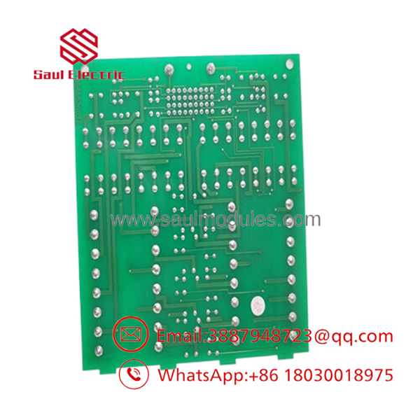
- NTR002
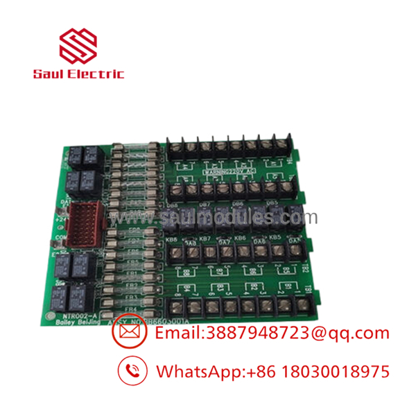
- NTR002
Installation & Configuration Guide
Stage 1: Pre-Installation Preparation
- Estimated Time: 15 minutes
- ⚠️ Safety First: Confirm that the redundant path of the control ring is fully operational before servicing this unit. Breaking both paths concurrently will isolate the Process Control Unit (PCU) from the OIS operator consoles, blocking active monitoring.
- Tools Required: Grounded anti-static wrist strap, small slot-headed screwdriver, clean dry cloth, digital multimeter.
- Data Backup: Document the physical cabling orientation—clearly identify which lines are assigned to Link A (Primary) and Link B (Secondary), and note whether they are configured for Coax or Twinax.
Stage 2: Removing the Old Module
- Estimated Time: 10 minutes
- Steps:
- Clip your ESD grounding strap to the enclosure frame.
- Disconnect the 24 V DC power feed terminal plug from the board interface.
- Carefully disconnect the BNC bayonet cables or unscrew the twinaxial signal wires from the Link A and Link B headers. Tag each wire line to prevent crossing links during reinstall.
- Disconnect the ribbon routing cables (e.g., NKLS01 or NKPL01) linking the termination unit to the rack-mounted controller interface modules.
- Unbolt the mounting and grounding screw components attaching the PCB to the NFTP01 backplate assembly, then lift the old board free.
Stage 3: Installing the New Module
- Estimated Time: 15 minutes
- Steps:
- Position the replacement NTR002 on your anti-static work pad.
- Configuration Clone (Critical step): Inspect the jumper layout blocks on the replacement board. You must set the selection jumpers to match the physical medium (Coaxial position or Twinaxial position) independently for both Link A and Link B paths to mirror the existing setup.
- Slide the circuit board onto the chassis mounting alignment pins on the termination panel.
- Tighten the frame mounting screws, ensuring the critical grounding point makes solid contact with clean metal.
- Reattach the NKLS/NKPL ribbon cables to their respective module ports.
- Reattach the Link A and Link B network media cables securely to their respective terminal block slots or BNC barrels.
- Self-Checklist:
- [ ] Media selection jumpers for Link A and Link B match the site network medium
- [ ] Chassis ground screw is tight
- [ ] Redundant network lines are mapped correctly without Link A/B crossovers
Stage 4: Power-On & Testing
- Estimated Time: 10 minutes
- Pre-Power Check: Use a multimeter to verify that the incoming 24 V DC terminal lines display correct polarity.
- Power-On Steps:
- Plug the 24 V DC power connector back into the card.
- Confirm that the internal rack power supply does not register a localized fault condition and that the board’s onboard fuse remains intact.
- Verify the diagnostics on the companion INNIS module. The network interface status display should indicate that both Link A and Link B loops are initialized and synchronized.
- Perform a manual network loop-switch test via the console software to ensure data switches correctly between the primary and secondary channels without dropping packets.
- ⚠️ Troubleshooting Note: If the system triggers a “Link B Open” alarm immediately following installation, check the BNC connection tightness on the Link B channels or inspect the jumper orientation. An unseated jumper will leave that specific link un-terminated, creating an open-circuit state on the token ring.
Frequently Asked Questions (FAQ)
What is the operational difference between the NTCL01 and the ?
The NTCL01 is designed for single-channel, non-redundant INFI-NET/Cnet network connections. The is specifically engineered to handle redundant network paths, featuring split internal circuitry and dedicated physical connections for both Link A and Link B loops. It ensures data traffic shifts over to the alternative line if one cable path is severed.
Can I run Link A using coaxial cable and Link B using twinaxial cable on the same ?
Technically yes. Because the configuration jumpers for Link A and Link B are separate blocks on the PCB, you can set one channel to Coax mode and the other to Twinax mode. However, this asymmetric setup is rarely recommended in standard industrial configurations due to variations in signal propagation delays and cable impedance parameters.
What should I check if both network channels show data failure errors after installation?
Check the chassis grounding screw. The relies on its direct structural connection to the NFTP01 termination panel to drain induced high-frequency electromagnetic noise. If the mounting screws are loose, or if there is corrosion on the panel plate, common-mode noise can disrupt the data streams on both loops simultaneously.
Does the contain firmware parameters that must be updated?
No. The functions as a hardware-level signal routing and media interface termination unit. It contains no microprocessor, operational firmware, or configuration registers. All channel setup is managed physically via the onboard hardware jumper settings.
What causes the onboard fuse to clear on this unit?
The onboard fuse typically blows due to field wiring issues, such as a short circuit between the incoming 24 V DC auxiliary line and the cabinet frame, or an internal component failure within the connected network interface module via the ribbon cable connection. Always isolate the power source and test for line-to-ground shorts before replacing the fuse.



 Start Chat


