





Description
Key Technical Specifications
| Parameter | Value |
| Model Designation | PDP800 |
| Microprocessor | ColdFire 32-bit processor running at 160 MHz |
| Onboard Memory | 128 MB RAM, 4 MB ROM, 4 MB Flash |
| Input Power Supply | 24 V DC (\pm10%) |
| Power Consumption | Typical 3.6 W (150 mA at 24 V DC) |
| Bus Interface Connection | HN800 redundant 4 Mbps I/O bus |
| Supported Protocols | PROFIBUS DP-V0, DP-V1, DP-V2 (PA supported via DP/PA linking devices) |
| Line Transmission Speeds | 9.6 kbps up to 12 Mbps |
| Physical Interface | 2x redundant PROFIBUS DP 9-pin D-Sub connectors (on PTU810 base) |
| Physical Dimensions | 124 mm (W) x 186 mm (H) x 127 mm (D) (when installed on base) |
| Operating Temperature | 0 to 55°C (32 to 131°F) |
| Diagnostic Interface | 1x mini-USB port on module front plate |
Product Introduction
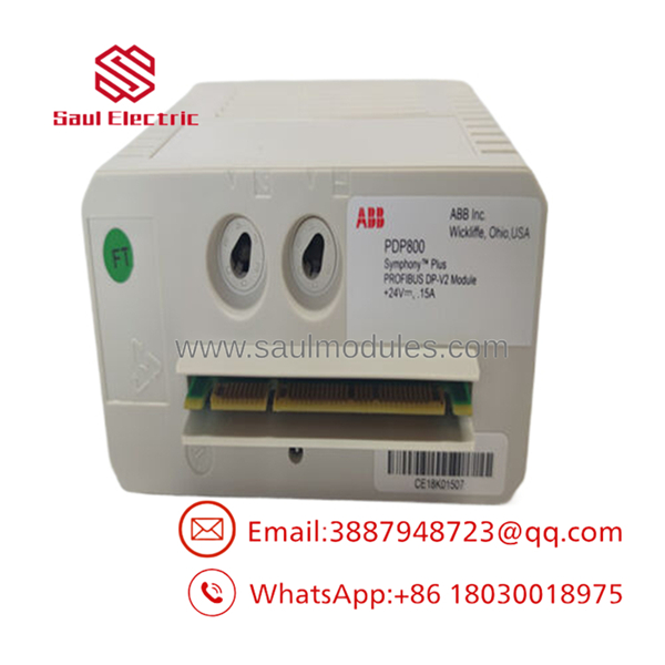
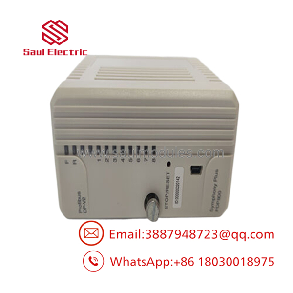
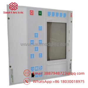
The ABB PDP800 is a high-performance PROFIBUS DP master interface module designed for the Symphony Plus SD Series control platform. Serving as the dedicated gateway between SPCxxx series controllers and intelligent field instruments, the PDP800 enables real-time integration of smart transmitters, actuators, motor control centers (MCCs), and other third-party DP/PA devices without burdening the controller’s main processing unit.
Powered by a 32-bit ColdFire processor, the module fully supports the PROFIBUS DP-V2 specification, allowing for high-resolution 1-millisecond sequence-of-events (SOE) time-stamping directly at the device level. Built for high-availability systems, it supports module, power, and line-level media redundancy. By utilizing its fiber-optic extension capabilities, networks can expand up to 15 kilometers, bridging the gap between localized process control and remote plant systems.
- PDP800
- PDP800
Installation & Configuration Guide
Stage 1: Pre-Installation Preparation
- Estimated Time: 15 minutes
- ⚠️ Safety First: Notify operations of potential network bus interruption before replacing or commissioning this card. Confirm that your system is configured with redundant PDP800 modules; if non-redundant, pulling this module will take down all downstream PROFIBUS communication. Lock out the 24 V DC primary auxiliary breaker feeding the target slot if you are not performing an active hot-swap.
- Tools Required: ESD wrist strap, small flathead screwdriver, laptop with S+ Engineering / Composer tool, mini-USB cable.
- Data Backup: Upload and save the active controller configuration. Take a physical photograph of the module slot and note the node address of the companion SPCxxx controller.
Stage 2: Removing the Old Module
- Estimated Time: 5 minutes
- Steps:
- Securely attach your grounded ESD wrist strap to the unpainted cabinet rail.
- If the module is running in a redundant pair and the secondary module has assumed the active role, you may hot-swap the unit. Confirm the status LED shows ‘Standby’ (or ‘Backup’) on the module you wish to replace.
- Loosen the upper and lower captive mounting screws on the front plate of the .
- Pull the module straight out of the PTU810 mounting base, taking care not to twist or apply side-load to the HN800 backplane connector.
Stage 3: Installing the New Module
- Estimated Time: 10 minutes
- Steps:
- Carefully unpack the replacement on your ESD mat.
- Confirm that the mechanical key positions on the module match the PTU810 base unit keys (Position 1 = A, Position 2 = A) to avoid inserting the wrong module type.
- Align the module guides with the base plate slots and push the module straight back into the base until it sits flush against the backplane connector.
- Securely tighten the top and bottom captive retaining screws to lock the physical assembly.
- Self-Checklist:
- [ ] Module keys match base receptacle layout
- [ ] Unit seated flush without catching backplane pins
- [ ] Captive front-plate screws are hand-tight
Stage 4: Power-On & Testing
- Estimated Time: 10 minutes
- Pre-Power Check: Ensure all field PROFIBUS 9-pin D-sub DB9 connectors are securely fastened and terminated on the base unit.
- Power-On Steps:
- Turn on the 24 V DC power feed if it was isolated.
- Watch the front-plate LEDs. The module will execute a self-test sequence. The green POWER LED should turn solid, and the status LEDs should indicate active or standby operational modes depending on whether a redundant partner is present.
- Connect your engineering laptop to the mini-USB diagnostic port on the front panel to verify current firmware versions.
- Use the engineering system diagnostics to push the configuration to the module if it does not automatically synchronize from the active redundant controller.
- ⚠️ Troubleshooting Note: If the red “ERR” LED stays on, there may be a firmware version mismatch between the newly inserted module and the existing controller framework. Use the mini-USB diagnostic port to flash the board to match the project’s target runtime baseline.
Frequently Asked Questions (FAQ)
Is the module truly hot-swappable while the plant is operating?
Yes. The supports active hot-swapping when configured in a redundant pair on a redundant mounting base (such as the PTU810). If one module fails, its redundant partner automatically takes over communication within milliseconds. You can remove the failed unit, insert the replacement, and the active module will automatically synchronize the operational configuration to the new unit without interrupting field communication.
Can I connect PROFIBUS PA instruments directly to the ?
Not directly. The physical ports on the base are designed for RS-485-based PROFIBUS DP electrical signaling. To connect PROFIBUS PA (Process Automation) devices, which operate on the MBP physical layer (Manchester Coded, Bus Powered), you must route the DP line through a standard DP/PA linking device or segment coupler.
What is the difference between the and the PDP800A?
The difference lies in environmental protection. The is designed for standard industrial control cabinets compliant with ISA S71.04 G1 classifications. The PDP800A features an upgraded conformal coating process that meets the stringent ISA S71.04 G3 class, providing resistance against corrosive chemical vapors and high relative humidity levels, making it the preferred choice for petrochemical and pulp/paper processes.
How does the module handle line redundancy?
The mounting base has two distinct DB9 serial ports to support PROFIBUS DP line redundancy. The continually monitors both cable paths. If a cable break occurs on Line A, the module’s transceiver seamlessly transitions traffic to Line B without dropping the connected slaves or halting controller execution.
What causes a “Configuration Mismatch” error after plugging in a new module?
This usually occurs when the firmware version programmed on the replacement ‘s flash memory does not match the version expected by the SPCxxx controller. Connecting a PC via the front USB port allows you to read the module’s current version and load the matching operational image using the S+ Engineering software suite.

 Start Chat


