





Description
Key Technical Specifications
| Parameter | Value |
| Model Designation | PHARPS32000000 |
| Sub-assembly Hardware Code | F8G2B3B6 |
| System Compatibility | Bailey INFI 90 / Symphony Plus Harmony (S+ HR) systems |
| Input Voltage Range | 90 to 264 V AC (wide range auto-selection) |
| Input Frequency Range | 47 to 63 Hz |
| Power Consumption | 1,150 VA maximum at full load |
| Output DC Rails | • 5 V DC @ up to 60 A
• +15 V DC @ up to 3 A • –15 V DC @ up to 3 A • 24 V DC @ up to 17 A |
| Continuous Output Capacity | ~320 W total output power across all rails |
| Protection Features | Built-in overvoltage clamp, short-circuit foldback, and thermal protection |
| Cabinet Footprint | Designed for slide-in integration into MPS III Power Chassis |
| Operating Temperature | -20 to +70°C (-4 to 158°F) |
| Physical Dimensions | 228.6 mm (H) x 330.2 mm (D) x 635 mm (W) |
| Net Weight | 5.9 kg (13.0 lbs) |
Product Introduction
The ABB PHARPS32000000 (featuring sub-assembly code F8G2B3B6) is a high-capacity, multi-output DC power supply module engineered for the Bailey INFI 90 and Symphony Plus Harmony (S+ HR) legacy DCS platforms. Operating as the heart of the Modular Power System III (MPS III), this slide-in module converts wide-range AC mains into highly regulated DC power rails to simultaneously energize system processors, communication cards, analog I/O circuits, and field devices.
Built for continuous 24/7 industrial plants, the PHARPS32000000 delivers dedicated 5 V DC, \pm15 V DC, and 24 V DC outputs from a single integrated chassis. It features advanced galvanic isolation, noise suppression, and protection mechanisms designed to prevent line-side transients from damaging sensitive downstream backplanes. The module is fully compatible with redundant power configurations, allowing seamless power-sharing and high fault tolerance in critical process loops.
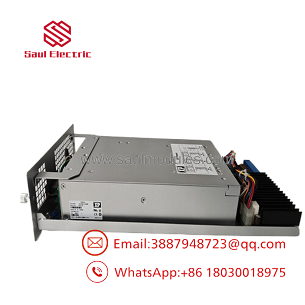
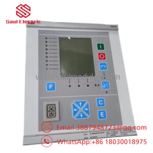
- PHARPS32000000 F8G2B3B6
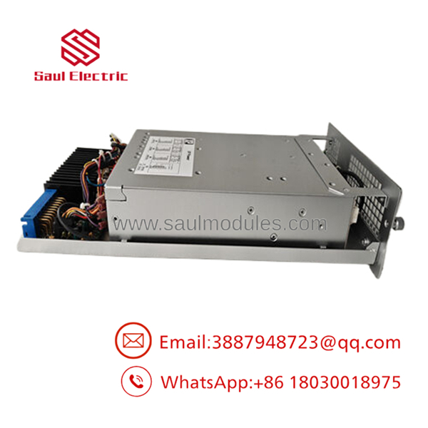
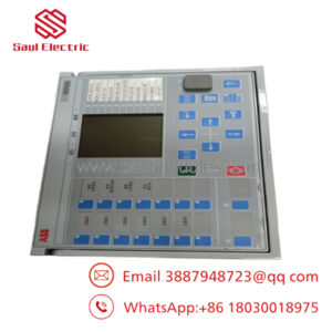
- PHARPS32000000 F8G2B3B6
Installation & Configuration Guide
Stage 1: Pre-Installation Preparation
- Estimated Time: 15 minutes
- ⚠️ Safety First: Disconnect the primary AC mains breaker feeding the power cabinet frame before attempting installation. If you are operating in an N+1 redundant configuration, verify that the remaining online power modules have sufficient capacity to carry the full current draw of the rack before pulling the faulty unit.
- Tools Required: ESD wrist strap, flathead screwdriver, insulated digital multimeter, cross-point screwdriver (for chassis locking tabs).
- Data Backup: No configuration backups are required; the power supply uses analog circuitry and does not store parameter maps or network logic.
Stage 2: Removing the Old Module
- Estimated Time: 10 minutes
- Steps:
- Wear your grounded ESD wrist strap and bond it to the cabinet chassis.
- Switch off the local AC switch located on the front panel of the power module (if equipped).
- Loosen the upper and lower captive locking screws holding the unit into the MPS III chassis frame.
- Slide the heavy power module straight out of the slot along the guide rails. Caution: Hold the module firmly underneath as it clears the chassis, as it weighs approximately 5.9 kg.
- Inspect the chassis backplane connector for any signs of arcing, dust accumulation, or bent alignment pins.
Stage 3: Installing the New Module
- Estimated Time: 10 minutes
- Steps:
- Carefully unpack the replacement PHARPS32000000.
- Verify that the rear busbar connection blades are clean and free of oxides or shipping grease.
- Slide the new power module into the empty chassis bay, keeping it level along the guide tracks. Push firmly at the end to fully engage the rear plug-in bus connector.
- Tighten the physical captive screws on the module’s faceplate to lock it into the frame securely.
- Self-Checklist:
- [ ] Unit is fully seated flush against the backplane receiver
- [ ] Cabinet locking tabs are securely engaged
- [ ] Faceplate mounting screws are snug
Stage 4: Power-On & Testing
- Estimated Time: 15 minutes
- Pre-Power Check: Verify with a multimeter that there are no low-resistance short circuits from the 24 V, 15 V, or 5 V output terminals to the cabinet ground.
- Power-On Steps:
- Turn on the primary AC breaker feeding the power tray.
- Turn the module’s front power switch to the ON position.
- Observe the front-panel status indicators:
- Green POWER ON LED: Should illuminate immediately.
- Amber/Red FAULT LEDs: Should remain off (any active fault lights indicate a failure on the corresponding DC rail).
- Use a multimeter to measure the test points on the front of the board, confirming the 5 V DC, \pm15 V DC, and 24 V DC outputs are within a \pm2% regulation tolerance under active system load.
- ⚠️ Troubleshooting Note: If the 5 V DC rail fault LED illuminates, check the processor racks. A failed controller card can place an excessive current load on the 5 V rail, triggering the short-circuit foldback protection of the . Isolate the rack cards sequentially to locate the short.
Frequently Asked Questions (FAQ)
Can the be hot-swapped while the DCS is running?
Yes, but only if configured in a redundant N+1 layout. If your MPS III power chassis contains two or more operational modules sharing the power load, you can pull a single failed unit and slide in the replacement without shutting down the plant. Ensure the remaining units are not operating near their maximum limit before removing the failed supply.
What is the meaning of the “F8G2B3B6” code on my unit?
The code F8G2B3B6 represents the specific hardware revision and sub-assembly configuration of the internal power board circuitry. When replacing legacy power units, matching this revision code ensures that the electrical filtering characteristics, component tolerances, and physical backplane alignments are identical to your existing modules.
Why does this power module provide so many different DC output rails?
Legacy DCS platforms like Bailey INFI 90 rely on multiple bus architectures. The 5 V DC rail is required to power the digital logic and microprocessors on the controller cards; the \pm15 V DC rails are used for high-precision analog operational amplifiers within your I/O interfaces; and the 24 V DC rail is needed for field loop power, relays, and optical transmitters.
My replacement unit makes a faint humming or high-pitched squealing sound. Is this normal?
No. While large transformers may emit a faint, low-frequency hum, a high-pitched squealing sound indicates that the internal switching regulators are operating under abnormal load conditions or suffering from aging filter capacitors. If a newly installed unit squeals, verify that you are not overloading one of the specific voltage rails or check the unit’s grounding path.
Does this power supply contain batteries or require parameter programming?
No. The is a purely hardware-driven power conversion module. It contains no software, parameter settings, or memory chips. You do not need to configure communication protocols or restore firmware backups. It is a true plug-and-play unit.

 Start Chat


