





Description
Key Technical Specifications
| Parameter | Specification / Value |
| Model Number | REF541KB115AAAA |
| Product Series | REF 541 / Feeder Terminal |
| Functionality Level Code | K (Advanced Control & PLC capabilities) |
| Protection Software Suite | B (Basic/Standard protection software package) |
| Hardware Variant Configuration | 115 |
| Auxiliary Operating Voltage (U_{aux}) | 110–240 V AC / 110–240 V DC |
| Nominal Voltage Inputs (U_n, U_o) | 100 V, 110 V, 115 V, 120 V (phase-to-phase and residual) |
| Nominal Current Inputs (I_n) | 1 A / 5 A (main phases); 0.2 A / 1 A (sensitive earth-fault) |
| Rated Frequency (F_n) | 50 Hz / 60 Hz (auto-detectable/configurable) |
| Harmonic Measurement Range | Up to the 13th harmonic (for Power Quality monitoring) |
| Communication Protocols | SPA, LON, Modbus RTU, IEC 60870-5-103, Profibus-DP, IEC 61850 |
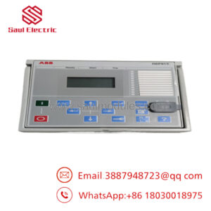
| Human-Machine Interface (HMI) | Integrated LCD graphic display with programmable bay MIMIC |
| Dimensions (W x H x D) | 223.7 mm x 265.9 mm x 235 mm |
| Net Weight | 9.50 kg (20.94 lbs) |
Product Introduction
The ABB REF541KB115AAAA is an advanced, numerical feeder protection and control terminal belonging to the versatile REF 54_ series. It is designed to deliver unified protection, control, metering, and system supervision for medium voltage utility and industrial distribution networks. It handles radial, loop, or mesh networks with isolated, resonant-earthed, or earthed neutral schemes.
The “KB115” configuration combines the specialized, programmable Control (K) software profile with the solid, baseline Protection (B) suite. This specific setup enables the device to act as an all-in-one control bay manager, executing complex interlocking schemes, control logic, and circuit-breaker monitoring, alongside highly selective multi-stage overcurrent, directional earth-fault, and thermal overload protection. This minimizes the need for auxiliary relays and complex hardwired interlocks inside the switchgear cabinet.
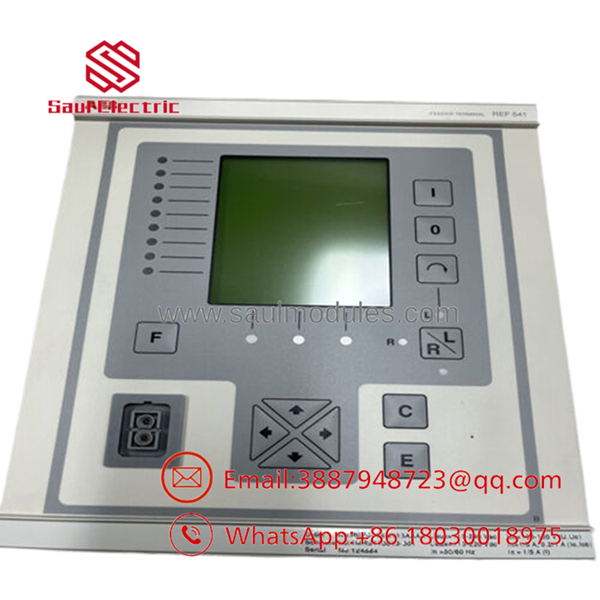
- REF541KB115AAAA
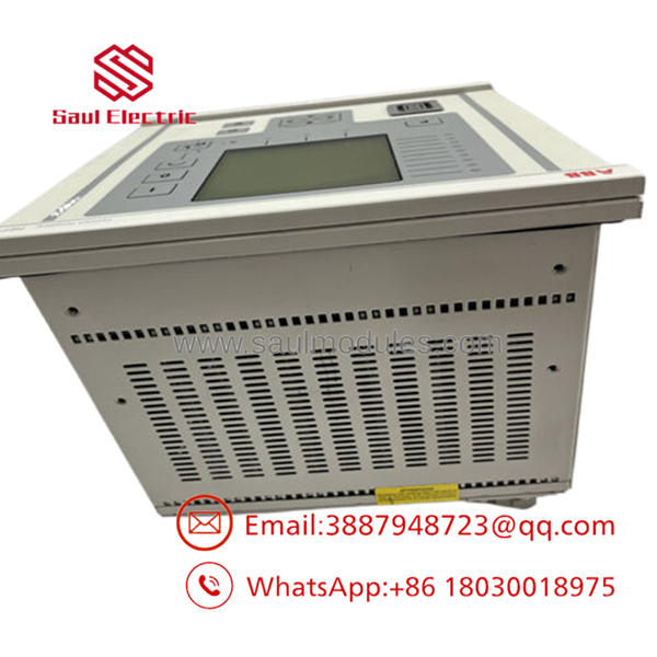
- REF541KB115AAAA
Technical Configuration Code Breakdown
To understand exactly what is integrated inside the physical assembly of the REF541KB115AAAA variant, reference the standard ABB ordering code breakdown:
Installation, Alignment, & Commissioning SOP
Because the REF541 is a high-security protective relay, replacement must follow a rigorous, sequenced procedure.
Step 1: Isolation & Safety Protocols (Est. Time: 15 minutes)
- ⚠️ Danger: High voltages are present on the current transformer (CT) and voltage transformer (VT) secondary circuits. Never open-circuit a live CT secondary circuit. Doing so generates extremely high inductive voltages that will destroy the relay and cause fatal electrical shocks.
- Put the feeder circuit breaker into the “Test” or “Disconnected” position. Lock out and tag out (LOTO) the breaker control circuits.
- Short-circuit all external CT secondary lines using a dedicated terminal shorting block before disconnecting the back terminal plugs.
- Isolate the VT inputs by pulling the associated secondary protection fuses.
- Turn off the 110–240 V AC/DC auxiliary power supply feeding the terminal.
Step 2: Swap the Hardware (Est. Time: 15 minutes)
- Ensure your ESD wrist strap is grounded.
- Unplug the terminal blocks on the rear panel of the failed relay. Note that the heavy-duty CT/VT terminal connectors feature auto-shorting mechanisms on some blocks, but physical wire-shorting blocks must still be verified.
- Loosen the panel-mounting clamp screws located on the sides of the bezel.
- Pull the REF541 unit out of the switchgear cutout.
- Insert the new REF541KB115AAAA into the cutout, align the rubber sealing gasket, and secure the side mounting clamps to 2.5 Nm of torque to ensure dust and moisture isolation.
Step 3: Rewire & Verify Connections (Est. Time: 15 minutes)
- Reconnect all control, digital input/output, and communication plugs.
- Connect the earth terminal (ground terminal) on the rear chassis of the relay to the main switchgear copper ground bar using a low-impedance copper wire (minimum cross-section 4.0 mm^2).
- Remove the temporary shorting pins on the external CT block only after ensuring the CT plug is firmly seated and screwed into the rear of the new REF541 unit.
Step 4: Configuration & Parameter Flashing (Est. Time: 20 minutes)
- Energize the U_{aux} power supply (110–240 V).
- The green “Ready” LED on the front HMI should turn solid green after completing its self-test.
- Connect your engineering laptop to the optical front panel port (using the specialized SPA-ZP optical-to-RS232 interface cable) or the rear service port.
- Use CAP 505 or PCM600 software to load your archived
.mimconfiguration, logic block configurations, and protection settings (current curves, times, CT/VT scaling factors) directly onto the new unit. - Perform a complete primary or secondary current injection test on all phases to verify that the relay accurately reads active line current and executes trip outputs correctly.
Frequently Asked Questions (FAQ)
What is the default password to access local settings on the front panel?
For ABB REF541 units, the default factory-level passwords depend on the access tier. Typically, the default password for the “Technical” level (which allows parameter editing) is 10. For the standard Operator level, it is 1. These parameters are usually changed during initial substation commissioning for cyber-security compliance, so refer to your plant’s internal security registry if the defaults fail.
Can I replace a with a REF541KB127AAAA?
No, not without modifying the system wiring. The last digits (115 vs 127) designate completely different physical hardware and terminal layouts. A “127” variant has a different density of binary input/output channels, meaning the physical wire bundles on your switchgear panel will not map to the same terminal points, causing physical connection mismatches and logic failures.
Why is my relay showing a “Trip Circuit Supervision (TCS)” alarm after installation?
The TCS alarm indicates that the relay has detected a break or loss of voltage in the external circuit-breaker trip coil circuit. This is common right after a replacement if:
- The external trip circuit fuse is still open/swallowed.
- The bypass resistor on the digital input terminal assigned to TCS monitoring is missing or improperly connected.
- The circuit breaker is racked out, opening the auxiliary contacts.
How do I configure the visual graphic display (Mimic) on the front of the REF541?
The graphical bay mimic (showing single-line diagrams of disconnectors and breakers) is drawn and compiled using the MIMIC Editor tool inside the CAP 505 / CAP 501 engineering suite. Once designed on your PC, the mimic is uploaded as a structural binary file to the relay processor via the front optical communication port.

 Start Chat


