





Description
Key Technical Specifications
| Parameter | Value |
|---|---|
| Manufacturer | ABB |
| Model Designation | SS832 |
| Product ID | 3BSE018358R1 |
| Input Voltage Range | 22 to 30 V DC |
| Number of Inputs | 2 independent channels (for Power Supply A and Power Supply B) |
| Max Continuous Input Current | 2 × 20 A or 1 × 40 A |
| Output Voltage | Input voltage minus internal diode drop (Approx. 0.4 V DC drop) |
| Max Continuous Output Current | 40 A continuous |
| Peak Output Current | 60 A for a maximum duration of 10 seconds |
| Decoupling Mechanism | Integrated high-efficiency schottky diode array |
| Status Telemetry | 2 potential-free relay contacts for input voltage monitoring |
| Mounting Configuration | Wall mount or standard 35 mm DIN Rail |
| Operating Temperature | −25 to +60 °C (non-condensing) |
| Net Dimensions | 130 mm Depth × 136 mm Height × 56 mm Width |
| Net Weight | 0.82 kg |
Product Introduction & Supply Chain Strategy
The ABB SS832 (3BSE018358R1) is a heavy-duty, DIN-rail mounted power voting and redundancy module designed to establish high-availability power architectures for System 800xA controllers, communications buses, and S800 I/O racks. Operating as a solid-state decoupling matrix, the unit accepts two independent 24 V DC inputs—typically from paired SD834 or SD822 power supplies—and routes them into a single, high-capacity 40 A output rail. By utilizing high-efficiency internal diode networks, the SS832 ensures that if one upstream power source suffers an internal short circuit or localized component failure, the faulty rail is instantly decoupled without causing a voltage sag on the common distribution bus.
From a strategic procurement perspective, choosing this unit as a New Surplus asset optimizes your Total Cost of Ownership (TCO) while securing a critical reliability safety net. Because the redundancy voter handles the combined current load of the entire control cabinet, its internal decoupling diodes and telemetry signaling relays undergo continuous thermal and electrical stress. Sourcing a refurbished or second-hand alternative introduces significant risk; aged, heat-fatigued diodes can experience reverse-current leakage or fail shorted. This compromises your fault isolation capability and turns your redundancy system into a single point of failure. Investing in zero-hour surplus hardware ensures strict galvanic isolation and maintains absolute power security across your process loops.
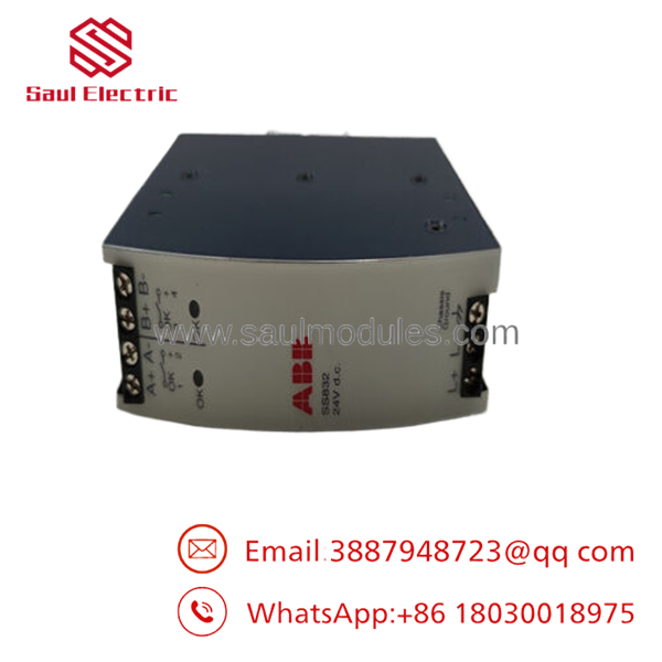
- SS832
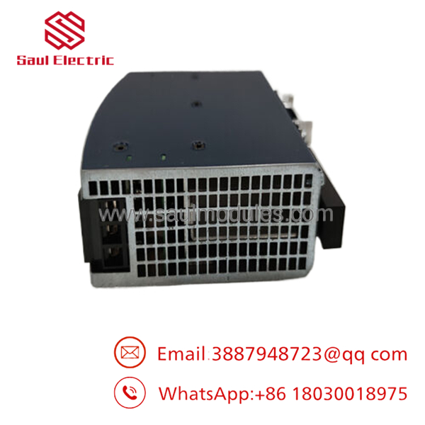
- SS832
Installation & Configuration Guide
Stage 1: Pre-Installation (Prep & Safety)
- De-energize both independent primary AC feeder lines feeding the upstream power supplies. Verify that all input lines read 0 V using a digital multimeter.
- Put on a grounded ESD wrist strap and connect it directly to the enclosure frame ground bar.
- Review the current consumption layout of your S800 I/O rack to confirm the total distribution draw does not exceed the 40 A continuous rating.
Stage 2: Removal
- Unfasten the screw terminals clamping the raw 24 V DC inputs from Power Supply A and Power Supply B.
- Disconnect the primary 40 A output rail lines and the small-signal telemetry alert wires linked to the module’s diagnostic contacts.
- Release the lower DIN rail retention clip using a flathead screwdriver, then pivot the module upward to detach it from the mounting rail.
Stage 3: Installation (Clone & Seat)
- Snap the new surplus SS832 onto the 35 mm DIN rail, checking that the internal metal grounding clip seats tightly against the rail surface.
- Strip the heavy-duty input and output wires back to the exact factory specification to prevent exposed copper strands.
- Terminate the connections into the screw blocks, ensuring you torque each wire to prevent high-resistance connection points that generate localized heat.
Stage 4: Power-On & Testing
- Re-energize Power Supply A only. Verify that the front panel LED for Channel 1 illuminates and check that the common output rail stabilizes at the correct voltage minus the standard diode drop.
- Energize Power Supply B and ensure that the Channel 2 LED illuminates. Adjust the output potentiometers on the upstream supplies so they sit within 50 mV of each other to establish uniform load sharing.
- Disconnect one supply breaker to confirm the voter handles the instantaneous transition without triggering a downstream process reset, then verify the status relay toggles to alert your SCADA interface.
Firmware/Software Versions & Upgrade Notes
The is an analog power-management device utilizing solid-state decoupling components and monitoring circuits. It does not include an internal microprocessor, flash memory blocks, or programmable firmware. Consequently, it operates independently of any active software applications running on your AC 800M or similar process control modules.
However, when configuring the power subsystem in your engineering control builder, you must configure the digital input loop monitoring the ‘s potential-free alarm contacts. Ensure your control software logic treats an open contact state on either redundancy monitoring channel as a high-priority maintenance alarm rather than a critical system trip. This configuration guarantees operators are alerted to fix a failed upstream power supply before a second failure causes an active station dropout.
Frequently Asked Questions (FAQ)
Is this voting module an original new unit or a repaired component?
This module is a guaranteed New Surplus item. It has never been installed in a live control panel, subjected to factory heat loading, or rebuilt. It has been preserved in temperature-controlled storage and opened exclusively for our internal inbound quality verification testing. We maintain a zero-tolerance policy for refurbished components.
Why does a new surplus voting module cost more than a standard refurbished model?
Redundancy modules are critical insurance assets for process continuity. Refurbished modules often hide degradation within their internal Schottky diode arrays and telemetry relay coils. If an aged diode in a refurbished unit fails under load, a fault on one power supply can pull down your entire control network. Sourcing a new surplus unit provides a fresh 10–15 year lifespan, eliminating the hazard of micro-faults and saving your plant from expensive unplanned downtime.
What is the exact purpose of the potential-free signal contacts on the module?
The features independent signal relay contacts that monitor the voltage status of Input 1 and Input 2. If either incoming power rail drops below the minimal operational threshold, the corresponding internal contact opens. This sends a real-time telemetry alert to your central DCS platform so maintenance teams can replace the failing power supply before the backup rail goes down.
Can I mix different power supply brands or sizes when running them through the ?
While the can decouple any two 24 V DC inputs up to its current limits, it is highly recommended to use identical, matched power supply modules (such as two ABB SD834 units). Mixing different power supply brands or current ratings makes balanced load sharing difficult, which can cause one unit to experience accelerated thermal wear.
What type of warranty coverage comes with this hardware component?
We provide a comprehensive 1-year warranty on this New Surplus voting module, starting from the day it leaves our warehouse. This matches the protective terms of standard factory components, ensuring reliable security for your spare parts inventory.


 Start Chat


