





Description
Key Technical Specifications
| Parameter | Value / Specification |
|---|---|
| Part Number | UFC921A101 / 3BHE024855R0101 |
| System Architecture | AC 800PEC (Power Electronics Controller) Framework |
| Onboard Intelligence | High-speed network co-processor with real-time logic routing |
| Communication Channels | High-density optical fiber ports, RJ45 Ethernet connection, serial links |
| Protocol Capabilities | Modbus TCP, Modbus RTU, Profinet, EtherNet/IP, PEC-bus links |
| Input Supply Voltage | 24 V DC (±15%), standard backplane derived |
| Diagnostics | Channel-specific LED error arrays and system monitoring registers |
| Coating Protection | Factory conformal-coated PCB for harsh industrial atmosphere protection |
| Operating Temperature | 0 to +65 °C |
| Weight | 1.32 kg |
Product Introduction
The ABB UFC921A101 3BHE024855R0101 is a high-performance fieldbus communication and interface processor card designed for the AC 800PEC power electronics controller family. This specialized board serves as the primary data-routing and protocol-translation bridge between the core real-time processing modules (such as the UFC760 controllers) and the wider plant-level networks or distributed peripheral I/O clusters. By decoupling communication tasks from the main control loop processor, it ensures high-speed data transmission without increasing controller scan times.
Engineers implement the UFC921A101 in demanding megawatt-class power electronics applications, including static synchronous compensators (STATCOM), synchronous condenser excitation packages, dynamic voltage restorers, and heavy industrial variable frequency drives. Equipped with both robust fiber-optic transceivers and standard copper network ports, this card handles high-bandwidth data transfers safely in areas prone to intense electromagnetic fields. Its fast protocol conversion engine enables real-time drive diagnostics and status tracking to be delivered straight to the plant DCS or SCADA layer.
Installation & Configuration Guide
Stage 1: Pre-Installation Preparation (Estimated Time: 15 minutes)
- ⚠️ Safety First: Isolate the control rack and the associated power electronics converter from all primary voltage sources and auxiliary power lines. High-power converter enclosures contain large capacitor banks that present a lethal shock hazard. Lock out and tag out (LOTO) all supplies. Wait a minimum of 15 minutes for the residual internal energy to discharge down to safe levels (<50 V) before removing chassis panels. Use a verified multimeter to ensure a complete zero-energy state.
- Tools Required: Grounded anti-static (ESD) wrist strap, Pozidriv PZ2 screwdriver, industrial-grade fiber-optic cleaning swabs and fluid, marking labels, smartphone.
- Data Backup: While the UFC921A101 acts primarily as a communication interface, it holds vital network routing tables, station node configurations, and IP assignments. Ensure you have an updated network topology configuration map and a full software backup of the master AC 800PEC project file before un-slotting the active unit.
Stage 2: Removing the Old Module (Estimated Time: 10 minutes)
- Secure your ESD wrist strap to a verified, unpainted metal ground point on the controller enclosure frame.
- Label all incoming copper Ethernet cables, serial connectors, and optical fibers. Fiber-optic lines must be reconnected to their exact original port pairings (TX to RX channels) during reassembly or communication will fail.
- Carefully unlatch and pull out the optical fibers. Immediately place clean protective dust caps over both the cable tips and the board’s open optical transceivers to prevent ambient contamination.
- Unplug the RJ45 and serial terminal lines from the faceplate interfaces.
- Loosen the captive retaining fasteners located on the upper and lower edges of the card faceplate. Slide the module out of its guide rails smoothly, holding it by the structural edges. Place it into a static-shielding bag.
Stage 3: Installing the New Module (Estimated Time: 15 minutes)
- Keep your ESD connection secure while removing the replacement UFC921A101 board from its factory anti-static box.
- Configuration Clone (Crucial): Locate any micro-dip switches or rotating address selectors on the surface of the PCB. Manually adjust these hardware controls to match the exact configurations of the old board. These switches establish the base hardware node identification, network baud rates, and bus termination choices.
- Align the module card edges with the plastic slot guides in the empty chassis cradle. Slide it straight inward until the backplane multi-pin plug is fully seated.
- Tighten the faceplate captive screws to secure the card and establish a low-impedance ground path back to the chassis frame.
- Clean the optical fiber cable ends using specialized lint-free swabs, remove the temporary dust caps, and plug each optical line back into its matching transceiver socket until it clicks. Re-insert the RJ45 and serial communication connections.
📋 Self-Checklist:
- [ ] All physical dip switch configuration arrays match the old card exactly.
- [ ] Fiber-optic connectors are cleaned, capped appropriately during staging, and fully seated.
- [ ] Captive mounting screws are tightened down completely to ensure proper system grounding.
Stage 4: Power-On & Testing (Estimated Time: 15 minutes)
- Re-apply the 24 V DC auxiliary control power feed to the control rack frame. Keep the primary medium-voltage bridge circuit completely isolated.
- Observe the front-panel status LEDs immediately. A normal startup sequence will transition to a stable green RUN indicator. If a red ERR or FAULT LED lights up, turn off power and check for network address conflicts or loose backplane connections.
- Connect your engineering laptop to the configuration port or log on via the supervisor network to verify the module’s presence in the controller hardware tree.
- Verify that the network link lights on the active Ethernet and fiber ports are flashing, indicating active, uncorrupted data traffic between the controller and the plant network layer.
- ⚠️ Troubleshooting Note: If the master processor reports a “Fieldbus Fault” or “Node Offline” status following power-up, check the physical node ID dip switches on the UFC921A101 board. A single incorrect toggle setting will prevent the module from responding to network polling.
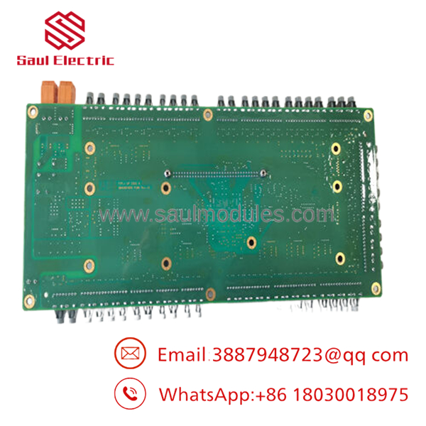
- 3BHE024855R0101
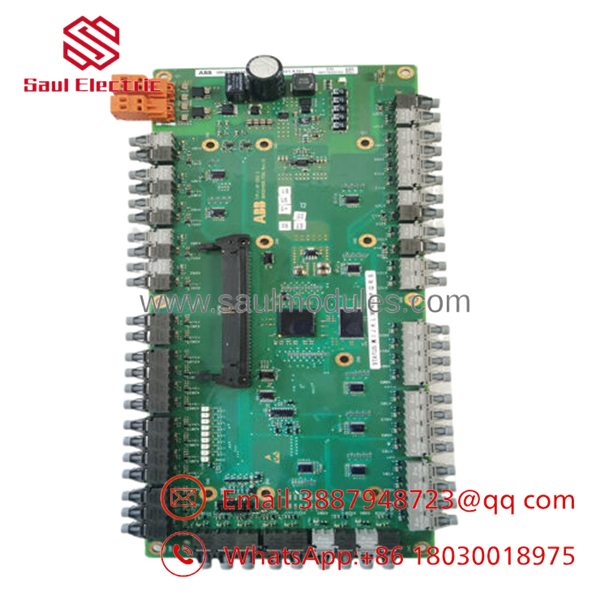
- 3BHE024855R0101
Frequently Asked Questions (FAQ)
Can the board be hot-swapped while the power converter is running?
Although it primarily handles communication traffic, pulling this card breaks the real-time telemetry link between the power semiconductor controllers and the overriding supervisory network. This sudden loss of data loop continuity will cause an immediate system shutdown and can trigger severe current transients inside the power bridge if commutation feedback is interrupted. Always place the system in a safe state and disconnect power before replacing the card.
What is the exact purpose of the factory part number 3BHE024855R0101?
The part number 3BHE024855R0101 represents the exact factory manufacturing code assigned by ABB for logistics, order fulfillment, and engineering trackability. While defines the generic functional model type and basic architecture variant, the 3BHE number guarantees that the hardware revision, electronic component layout, and protective conformal coating match your exact plant build standard.
Why is a conformal coating important on this specific module revision?
The is frequently deployed in demanding industrial environments, such as marine propulsion rooms, chemical manufacturing centers, and metal extraction mills. These locations often have high humidity, conductive dust, or trace corrosive gases in the air. The factory conformal coating provides a protective barrier over the sensitive circuit board components, preventing tracking faults, dendrite growth, and moisture degradation to ensure reliable operation over many years.
Does this replacement board come with our site-specific IP addresses pre-configured?
No. Replacement components obtained from factory stock or surplus warehouses are completely blank with respect to user-defined software setups. They contain only the base boot-level firmware. Upon physical installation, you must use the appropriate AC 800PEC toolset (such as Control Builder M or system engineering utilities) to download your site’s network parameters, IP address allocations, and fieldbus protocol mapping data.
What should I check if the Ethernet link light remains off after connecting the network cable?
If the network link light fails to turn on, check the following points: First, verify that the cable type (straight-through vs. crossover) matches the requirements of your switch or upstream connection device. Second, verify that the port speed and duplex settings on your network switch match the capabilities of the . Finally, ensure that the card is fully seated in the rack slot, as poor backplane contact can prevent the onboard network chips from powering up correctly.


 Start Chat


