





Description
Key Technical Specifications
| Parameter | Value |
| Manufacturer | ABB |
| Part Number (Model) | UNS0119A-Z,V1 (UNITROL 1020) |
| Catalog Number (PNC) | 3BHE030579R0003 |
| Excitation Output Current | 20 ADC continuous (at 55 °C ambient) |
| Maximum Ceiling Current | 40 ADC temporary peak capability |
| Supply Input Voltage | 9 to 300 VAC / 9 to 300 VDC auxiliary/shunt feed |
| Frequency Input Range | 10 to 500 Hz (supports variable speed applications) |
| Processor Architecture | Microcontroller-based dual-core digital control loop |
| Communication Protocols | Modbus TCP, Modbus RTU, CANopen |
| Analog Inputs / Outputs | Multi-channel configurable ±10 V / 0 to 20 mA interfaces |
| Digital Inputs / Outputs | Configurable 24 VDC logic channels |
| Operating Temperature | −40 to +70 °C (extended industrial range) |
| Protection Degree | IP20 minimal chassis envelope |
| Weight | 1.85 kg (compact, ruggedized enclosure) |
Product Introduction
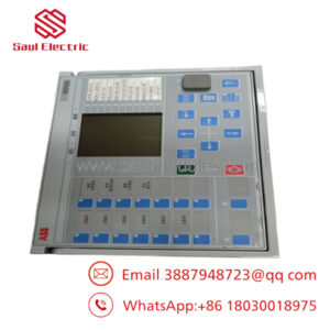
The ABB UNITROL 1020 UNS0119A-Z,V1 3BHE030579R0003 is a highly compact, microprocessor-driven Automatic Voltage Regulator (AVR) tailored for small to medium synchronous generators and industrial motors. Operating as a standalone or redundant excitation unit, this module dynamically controls the field current of a machine to stabilize terminal voltage, regulate power factors, and manage reactive power injections into the electrical grid during transient load drops or peak fluctuations.
Engineered with a powerful digital control core, the UNITROL 1020 replaces complex, older analog circuits with an integrated suite of limiters, including overexcitation, underexcitation, and stator current limiters. Maintenance teams rely on this module because it integrates standard communication bridges, like Modbus TCP and RS485, directly into the chassis. This layout simplifies remote diagnostic access and system monitoring while ensuring microsecond-level loop execution times that protect industrial power-generation infrastructure from voltage collapse.
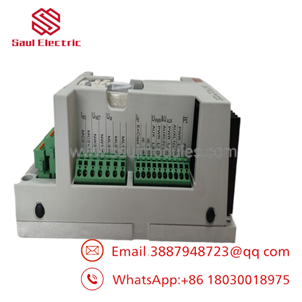
- UNITROL 1020 UNS0119A-Z,V1
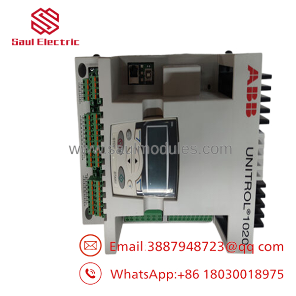
- UNITROL 1020 UNS0119A-Z,V1
Installation & Configuration Guide
Stage 1: Pre-Installation Preparation (Estimated Time: 15 Minutes)
- ⚠️ Safety First: AVR terminals carry dangerous electrical potentials during engine rotation. Coordinate a complete system lockout with your plant control room. Lock out and tag out (LOTO) the generator prime mover (diesel engine or gas turbine), prime mover starting batteries, auxiliary 24 VDC control breakers, and primary voltage transformer (VT) disconnect switches. Wait 5 minutes for internal filter capacitors to bleed down. Confirm a zero-energy state with a calibrated digital multimeter before disconnecting wire harnesses.
- Tools Required: ESD wrist strap, insulated precision flathead screwdrivers, wire stripping tool, wire markers, Windows laptop with ABB CMT1000 (Commissioning and Maintenance Tool) software installed, standard USB type-B connection cable.
- Data Backup: Connect your laptop to the active UNITROL 1020 unit using the CMT1000 tool via the USB or Ethernet interface. Export and archive the active configuration parameter profile (
.u1kfile extension), pid parameters, calibration constants, and event logger lists. Take clear reference photos of the physical terminal blocks and any grounding braids.
Stage 2: Removing the Old Module (Estimated Time: 10 Minutes)
- Secure your static-control (ESD) wrist strap to an unpainted, bare metal structural frame screw inside the AVR cabinet.
- Carefully unplug the detachable spring-cage or screw-type terminal blocks. Avoid putting physical stress on the wire entry points.
- Disconnect the communication links (RS485 serial networks, CANbus, or RJ45 Ethernet jumpers).
- Loosen the four structural mounting screws fixing the AVR chassis to the sub-panel baseplate, or release the DIN-rail locking clips at the base of the housing.
- Extract the module straight outward from the panel enclosure to prevent mechanical stress on surrounding components.
- ⚠️ Note: Keep the decommissioned regulator unit nearby on a static-safe mat to serve as a direct visual baseline during the replacement calibration process.
Stage 3: Installing the New Module (Estimated Time: 15 Minutes)
- Remove the new surplus UNS0119A-Z,V1 unit from its specialized anti-static packaging while maintaining secure wrist strap grounding.
- Align the mounting tabs with the pre-drilled panel holes (or position the module over the 35 mm top-hat DIN rail) and tighten all retaining anchors firmly to ensure secure mechanical grounding to the panel structure.
- Configuration Match (Crucial): Reconnect the terminal blocks, ensuring that the input signal leads match the terminal labels exactly. Pay close attention to terminal polarity for the excitation output pins (F+ and F-) and auxiliary power feeds.
- Plug in all required communication cables and check that the shield drain wires are properly grounded to the panel ground bar.
- Self-Checklist:
- [ ] AVR chassis is rigidly mounted and grounded to the panel frame.
- [ ] Terminal blocks are plugged in securely with no loose wire strands.
- [ ] Communication lines are connected with clear strain relief.
Stage 4: Power-On & Testing (Estimated Time: 25 Minutes)
- Pre-Power Check: Measure the resistance between the excitation output pins (F+/F-) and the panel frame ground to rule out any short circuits within the generator field winding.
- Power-On Steps:
- Energize only the local 24 VDC auxiliary control power supply or the external power grid feed. Do not start the generator engine yet.
- Monitor the diagnostic LEDs on the unit’s faceplate. The unit should clear its initialization sequence within 10 seconds, showing a stable green status lamp. A flashing amber or red LED implies a system fault or an unprogrammed parameter block.
- Connect your laptop to the AVR using the USB interface and open the CMT1000 software tool.
- Upload your archived
.u1kparameter file directly to the new regulator module, then click the “Save to Non-Volatile Memory” option. - Clear all active fault logs and perform a cold reboot of the AVR.
- Start the generator engine and ramp it up to its nominal idling speed. Activate the AVR via your software console and slowly increase the reference voltage, checking that generator terminal voltage tracks your commands accurately before synchronizing to the live electrical grid.
- ⚠️ Troubleshooting Note: If the AVR issues an immediate “Field Overcurrent” trip on startup, power down and verify that the generator field resistance matches the configuration limits defined in your CMT1000 parameter parameters.
Frequently Asked Questions (FAQ)
Can the UNITROL 1020 module be hot-swapped while the generator is operating?
No. Hot-swapping this module is completely prohibited. The UNITROL 1020 directly sources and controls the continuous DC excitation current (20 A) supplied to the machine’s rotor field. Disconnecting the module while online will cause an instant open-circuit spark, collapse the generator’s magnetic field, trigger a reverse power trip, and potentially destroy the internal power transistor (IGBT) stage inside the AVR. Always bring the engine to a dead stop before swapping components.
What is the exact difference between codes UNS0119A-Z,V1 and 3BHE030579R0003?
They refer to the identical industrial device. is the engineering type identifier that specifies the exact circuit layout, hardware revision, and internal processor configuration. 3BHE030579R0003 represents the specific global catalog part number (PNC) used by ABB logistics systems for spare parts handling. Both numbers must line up to guarantee a direct, drop-in replacement.
My unit has a “V1” suffix—is it backward compatible with non-V1 versions?
Generally, yes. The “V1” designation points to a internal hardware manufacturing lifecycle update that includes improved component layouts and updated core processing capabilities. However, you must use the matching version of the CMT1000 engineering tool to verify that your saved legacy parameter configuration files are properly mapped and converted before flashing them onto the new hardware.
Why does this unit cost less than ordering directly from standard factory channels?
We specialize in sourcing authentic New Original / New Surplus equipment outside standard distributor pipelines. These modules are acquired from canceled facility projects, excess plant warehouse overstocks, or industrial asset liquidations. This allows us to cut traditional markup fees and pass those direct procurement savings straight down to your plant maintenance budget.
What happens if the AVR stops working properly after installation?
Every UNITROL 1020 unit we sell includes a comprehensive 1-year replacement warranty starting from your delivery date. If the regulator encounters an unexpected hardware fault or component failure under normal, documented operating parameters within that 12-month period, we will ship out an identical replacement unit or issue a full refund if stock levels are exhausted.
Core Strategy 1: SOP Quality Transparency
To guarantee reliability on critical power systems and eliminate any doubts regarding surplus electronics, all incoming UNITROL 1020 AVR units pass through our strict multi-stage quality control process:
- Inbound Inspection & Traceability:
- Supply chains are audited against verified customs documentation and corporate asset records.
- Microscopic visual inspections confirm pristine PCB traces, untampered housing seals, factory-applied component lacquer coats, and clear, authentic serial plates.
- Internal assemblies are scanned to ensure all factory-provided connection terminal blocks and mounting accessories are included.
- Electrical Parameter Testing:
- Isolation barriers are evaluated using a Fluke 1507 insulation tester at 500 VDC across power inputs and terminal frames to confirm resistance levels exceed 10 MΩ.
- Loop grounding points are mapped to verify low-resistance paths, preventing noise coupling inside high-vibration engine panels.
- Live Functional Testing:
- The regulator is mounted on an authentic ABB test bench loop setup and fed by a clean, stabilized power source.
- Power-on self-test (POST) routines are analyzed to ensure normal processor boot times and accurate diagnostic LED states.
- Communication interfaces (Modbus TCP via RJ45 and Modbus RTU via RS485 terminal pins) are linked with automated testing software to verify full packet transmission without dropouts.
- The excitation output stage is coupled to an inductive dummy load bank and run continuously at its maximum 20 A load rating for 24 hours. Infrared thermal cameras are used throughout this burn-in test to screen for localized component hotspots.
- A detailed QC Test Report is saved for your records. Benchmark video coverage of your unit’s serial number under load can be provided by request before shipping.
- Firmware & Configuration Verification:
- The system operating system is read out, logged, and reset to the clean factory base build layer.
- Old application memory remnants are cleared out to ensure your engineers receive a completely fresh configuration slate.
- Final QC & Packaging Control:
- The supervising inspector cross-references all logs against compliance guidelines and signs the tracking traveler card.
- The AVR module is enclosed within an airtight, moisture-sealed anti-static (ESD) protective sleeve.
- The unit is packed with multi-layered, high-density bubble padding inside a thick corrugated shipping carton designed to withstand international air freight handling.
- A dated, tamper-evident “QC Passed” seal is affixed across the outer box closure.
Core Strategy 2: Technical Pitfall & Survival Guide
Replacing digital automatic voltage regulators requires careful attention to precision configuration. Avoid these 5 common field implementation traps:
- ❗ Mismatched Generator Parameter Profiles:
- The Trap: Booting up a new surplus AVR and applying live field excitation using factory default parameters can easily result in extreme overexcitation. This can trigger a generator overvoltage fault or burn out the exciter stator windings if the defaults don’t match your generator’s specific characteristics.
- Survival Strategy: Do not spin up the engine with a default configuration block. Always establish a USB connection to the AVR with the CMT1000 tool during the initial 24 VDC auxiliary power phase and load your verified, site-specific parameter file before running the machine.
- ❗ Inverted Excitation Output Polarity:
- The Trap: Accidentally swapping the positive (F+) and negative (F-) rotor excitation leads during terminal connection will cause the exciter field to oppose residual magnetism, preventing the generator from building up voltage on startup.
- Survival Strategy: Label every single wire lead explicitly prior to disconnecting the original unit. If the generator fails to build up voltage after installation, verify terminal polarity against your reference schematic instead of continually increasing manual excitation commands.
- ❗ Incorrect CT/VT Phasing Configuration:
- The Trap: Swapping the phasing lines between current transformers (CT) and voltage transformers (VT) can feed the AVR incorrect power factor data, leading to severe reactive power oscillations and system instability when running in parallel grid mode.
- Survival Strategy: Check and confirm that the voltage sensing phase sequence matches the current sensing phase direction exactly. Verify these vector alignments inside the tracking interface before attempting to synchronize the unit to a live utility grid.
- ❗ Poor Shield Grounding Layouts:
- The Trap: Leaving communication cable shields floating or improperly grounding them at both endpoints can introduce high-frequency electrical noise from surrounding switching equipment, leading to erratic analog signal readings or dropped Modbus packets.
- Survival Strategy: Ensure all twisted-pair communication shields are bundled cleanly and grounded at a single, dedicated low-impedance ground point inside the local panel enclosure to isolate data paths from common-mode noise.
- ❗ Neglecting Latent ESD Exposure:
- The Trap: Handling unshielded terminal connections without proper grounding equipment can expose sensitive internal microprocessor gates to silent electrostatic discharge. This can cause intermittent micro-processor resets or random logic lockups months after commissioning.
- Survival Strategy: Treat the regulator unit with care. Never touch raw terminal connection pins without an attached grounding strap. Complete all parameter configuration work on an approved anti-static workbench mat.


 Start Chat


