





Description
Key Technical Specifications
| Parameter | Value / Specification |
| Part Number | USC329AE01 / 3BHB002483R0001 |
| Platform Standard | AC 800PEC High-Speed Controller Environment |
| Synchronization Function | 3-Phase AC grid synchronization with digital Phase-Locked Loop (PLL) tracking |
| Measurement Resolution | 16-bit simultaneous analog sampling arrays |
| Grid Frequency Compatibility | 16.7 Hz, 50 Hz, 60 Hz nominal network profiles |
| Input Channels | Dedicated high-impedance 3-phase AC voltage and line current inputs |
| Optical Interfaces | Integrated high-speed fiber-optic links for low-latency firing loops |
| Power Consumption | Max 6.0 W from backplane supply rails |
| PCB Protection | Factory-applied industrial conformal coating |
| Operating Temperature | −10 to +60 °C |
Product Introduction
The ABB USC329AE01 3BHB002483R0001 is a high-precision, real-time synchronization and network measurement processing card developed for the AC 800PEC power electronics controller framework. The board serves as the core timing anchor for large power converter systems. It continuously samples incoming 3-phase grid voltages and executes a fast, hardware-embedded digital Phase-Locked Loop (PLL) to trace the exact phase angles, frequency shifts, and voltage vectors of the primary power grid.
This specialized tracking board is critical in megawatt-class power transmission and conversion installations, including Static Var Compensators (SVC), High-Voltage Direct Current (HVDC) light stations, hydro/gas turbine excitation systems, and active front-end (AFE) regenerative drives. The USC329AE01 uses localized 16-bit analog-to-digital processing to capture grid disturbances instantly. By outputting highly accurate phase timing references over dedicated fiber-optic channels directly to the gate driver units, it prevents thyristor or IGBT commutation failures during sudden grid voltage drops or phase shifts.
Installation & Configuration Guide
Stage 1: Pre-Installation Preparation (Estimated Time: 15 minutes)
- ⚠️ Safety First: Isolate the control rack and the associated converter system from all medium/high-voltage grid networks and auxiliary 24 V DC power sources. High-power converter compartments store lethal energy within their DC-link capacitor networks and potential transformer (PT) secondary terminals. Lock out and tag out (LOTO) all supplies. Wait a minimum of 15 minutes for internal stored energy to discharge down to safe voltage parameters (<50 V). Verify complete isolation with a calibrated multimeter before touching any backplane slots.
- Tools Required: Grounded anti-static (ESD) wrist strap, Pozidriv PZ2 screwdriver, fiber-optic cleaning tool kit, permanent marking labels, smartphone.
- Data Backup: The USC329AE01 works in tight tandem with the main system controller firmware. Before removing an operational board, verify that a complete, up-to-date backup of the drive parameters and control application files (compiled via MATLAB/Simulink or ABB Control Builder M) is saved on the engineering station.
Stage 2: Removing the Old Module (Estimated Time: 10 minutes)
- Fasten your ESD wrist strap and connect the ground clamp to a bare, unpainted surface of the metallic control cabinet frame.
- Label every analog input wiring block and fiber-optic link connected to the faceplate. The phase sequence connections (L1, L2, L3) are highly critical; reversing them will cause catastrophic misfiring when the drive is re-energized.
- Carefully detach the optical fiber plugs. Immediately place clean protective dust caps over both the cable tips and the board’s open optical transceiver ports to prevent airborne dust accumulation.
- Unplug the copper analog measurement terminal blocks from the card faceplate.
- Loosen the captive retaining fasteners located on the upper and lower edges of the card faceplate. Pull the board straight forward along its slot tracking lines, ensuring it does not rub against neighboring electronics. Immediately slide it into an anti-static bag.
Stage 3: Installing the New Module (Estimated Time: 15 minutes)
- Keep your ESD connection secure while removing the replacement USC329AE01 board from its factory static-shielding package.
- Configuration Clone (Crucial): Examine the surface of the PCB for manual micro-dip switch banks or rotary selectors. You must set these hardware switches to match the exact pattern of the old board. These switches govern specific input channel voltage attenuation factors, network node identification addresses, and grid frequency baselines (e.g., 50 Hz vs. 60 Hz).
- Align the module card edges with the slot guides in the empty rack channel. Slide it straight inward until the backplane plug engages completely with the rear cradle socket.
- Tighten the faceplate captive screws firmly to lock the card and establish a low-impedance ground path back to the chassis frame.
- Clean the optical fiber ends using a specialized lint-free tool, remove the temporary dust caps, and plug each optical line back into its matching transceiver socket. Re-attach the copper phase measurement terminal blocks securely.
📋 Self-Checklist:
- [ ] Physical dip switches are verified to match the original grid configuration.
- [ ] Analog input blocks are reconnected with the exact L1-L2-L3 phase orientation.
- [ ] All fiber-optic connectors are clean and fully clicked into their respective ports.
Stage 4: Power-On & Testing (Estimated Time: 20 minutes)
- Apply the 24 V DC auxiliary control power feed to the rack first. Keep the primary high-voltage power bridge and main line connections completely isolated.
- Observe the front-panel status LEDs immediately. A normal initialization sequence will move past internal self-tests to show a stable green RUN indicator. If a red ERR or FAULT LED lights up, turn off the system and verify your network address settings or look for a misaligned backplane plug.
- Access the engineering software console to check that the module is online and healthy in the controller hardware mapping tree.
- Energize the potential transformer (PT) input line lines safely. Verify that the phase tracking metrics, voltage amplitude readings, and frequency measurements reported by the USC329AE01 correspond exactly to your physical grid values before allowing the converter to gate.
- ⚠️ Troubleshooting Note: If the software throws an immediate “Phase Synchronization Error” or “Mains Out of Bounds” fault when grid sensing is enabled, check your analog input phase rotation. If L1/L2 or L2/L3 wires were crossed during installation, the digital PLL will fail to lock onto the grid.
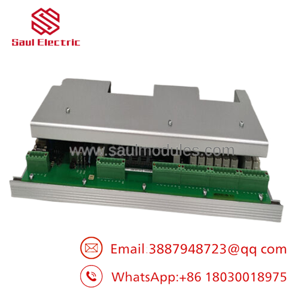
- 3BHB002483R0001
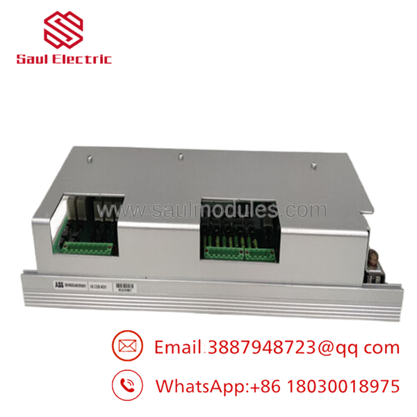
- 3BHB002483R0001
Frequently Asked Questions (FAQ)
Can the synchronization board be hot-swapped during active system load processing?
Because this card calculates real-time grid phase positions to synchronize thyristor and IGBT firing pulses, removing it mid-operation will break the firing timing sequence instantly. This will trigger an immediate high-energy system trip and can cause severe explosive damage within the power semiconductor components due to out-of-phase commutation. Always take the system completely offline before a swap.
What is the relationship between model code and part number 3BHB002483R0001?
is the technical hardware model definition code, representing the board family, circuit revision standard, and general functional grouping inside the AC 800PEC product hierarchy. The string 3BHB002483R0001 is the exact factory part number used for industrial sourcing, inventory asset tracking, and quality management. Both numbers must line up perfectly to guarantee a direct drop-in replacement that matches your plant’s documentation.
Why is the digital Phase-Locked Loop (PLL) on this board so critical for power plant installations?
Large industrial power electronics systems must switch current in perfect alignment with the utility grid’s AC sine wave. If the switching occurs even a fraction of a millisecond out of alignment, massive short-circuit currents can flow through the system. The high-speed digital PLL on the samples the grid continuously to lock onto its exact phase angle, allowing the system to maintain stable operation even during grid voltage drops, harmonics, and frequency spikes caused by external transmission line faults.
Does this replacement board come with our site-specific voltage scaling parameters pre-configured?
No. Factory new or surplus replacement modules are delivered containing base system firmware only. They do not possess your site’s specific potential transformer (PT) ratios, calibration factors, or threshold limits. These software variables must be compiled and downloaded to the unit from your central engineering workstation toolset once the card has been physically mounted and verified.
How can I verify if a synchronization fault is caused by a hardware failure on the or an actual grid disturbance?
If the grid is stable but the consistently reports synchronization loss, check the card-edge diagnostic logs via your engineering terminal. If the board’s internal 16-bit analog-to-digital converters (ADCs) are failing, or if the internal PLL cannot lock under a clean test signal from an external signal generator, the card’s input measurement circuit is likely damaged and requires a hardware replacement.

 Start Chat


