





Description
Key Technical Specifications
| Parameter | Value / Specification |
|---|---|
| Model / Part Number | VP01 / 2VAA008172R01 (Coated Version: 2VAA008172R011 / VP01A) |
| Module Type | Intelligent Turbine Valve Positioner |
| I/O Sub-System | Symphony Plus SD Series I/O |
| Response Time | < 1.0 millisecond (Input-to-Output updates) |
| Control Modes | Closed-loop (Proportional-Integral or Proportional-Only), Open-loop |
| Coil Driver Output | 2 Channels, up to 502 mA maximum per servo coil output |
| Position Feedback Types | AC LVDT (1.05–8.96 VRMS, 400–15,000 Hz)
Unipolar DC (0 to +12 V) / Bipolar DC (±6 V or ±12 V) Standard 4–20 mA transducers |
| Auxiliary I/O Channels | 2x Analog Outputs (4-20 mA), 1x Analog Input, 3x Digital Inputs (24 VDC), 2x Digital Outputs (Form A, max 400 mA) |
| Resolution | 16-bit high-precision converter matrix |
| Redundancy Support | Yes (Supports fully redundant channel pair tracking) |
| Form Factor / Mounting | Standard 190 mm / Horizontal Row or Vertical Column DIN-Rail |
Product Introduction
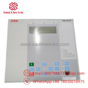
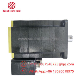
The ABB VP01 (Part Number 2VAA008172R01) is a specialized, high-speed valve positioner module designed within the Symphony Plus SD Series Distributed Control System (DCS) architecture. This module provides critical control over the flow of steam, gas, or water through a turbine by precisely regulating the physical positioning of the inlet throttle and governor valves. It interfaces directly with hydraulic actuators, modulating hydraulic fluid pressure via electro-hydraulic servo valves or I/H (current-to-pressure) converters.
Engineers specify the VP01 for large-scale utility power turbines and industrial mechanical drive governors where millisecond-range processing is required. Boasting a sub-1ms input-to-output update loop, the card coordinates tight Proportional-Integral (PI) control matrices. To ensure maximum uptime and precision, it accommodates redundant linear variable differential transformers (LVDTs) for cross-checked position feedback. Its rugged, low-power DIN-rail form factor allows it to operate reliably in harsh, high-vibration turbine cabinet environments without the need for forced enclosure cooling.
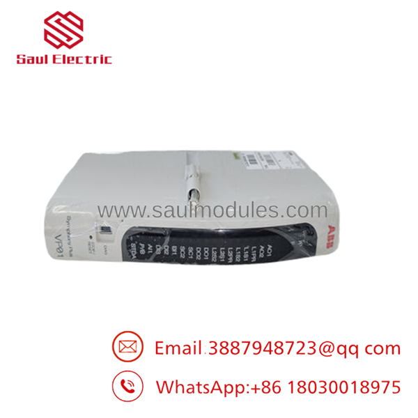
- VP01
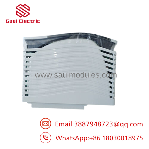
- VP01
Installation & Configuration Guide
Stage 1: Pre-Installation Preparation (Estimated Time: 15 minutes)
- ⚠️ Safety First: Notify plant dispatch and trip the turbine system before servicing the valve positioning loops. The VP01 directly commands massive hydraulic forces. Manipulating loop connections on an active turbine can cause uncontrollable overspeed events or immediate trip-outs.
- Tools Required: Grounded anti-static (ESD) wrist strap, small flat-head precision terminal driver, digital multimeter, S+ Engineering laptop toolset.
- Data Backup: Ensure your current S+ Engineering project database and the parent controller configuration files are completely backed up. Note down the specific tuning constants (Kp, Ki) assigned to the specific valve assembly you are targeting.
Stage 2: Removing the Old Module (Estimated Time: 5 minutes)
- Attach your grounded ESD wrist strap to a bare metal section of the cabinet chassis.
- If working on a hot-swappable redundant module pair, verify that the active partner card has taken over 100% of the drive control load.
- Loosen the physical retention clips or screws securing the housing to the modular base or slot carrier.
- Smoothly pull the module straight out of its backplane connection path. Do not torque or twist the module during extraction to prevent fracturing terminal guides. Place it into a static shielding bag.
Stage 3: Installing the New Module (Estimated Time: 10 minutes)
- Keep your ESD grounding connection intact while pulling the replacement out of its factory box.
- Configuration Clone (Crucial): If applicable, check any physical hardware address selectors on the mounting base or verify firmware alignment printed on the card labels. Coated variants (VP01A) must match the physical target environment slots.
- Slide the 190mm module into its vertical or horizontal slot channel, pushing firmly until it seats squarely into the backplane bus socket.
- Engage the structural locking clips on the top and bottom of the module casing until they click home.
📋 Self-Checklist:
- [ ] Module is locked into the base frame with zero physical wiggle room.
- [ ] Verification completed that LVDT sensing lines and servo coil leads match port mappings.
- [ ] Redundant configuration links are established if paired with a secondary active card.
Stage 4: Power-On & Testing (Estimated Time: 20 minutes)
- Apply control power to the I/O base track. Monitor the front status LEDs immediately. A healthy module will complete its self-test and display a solid green status indicator.
- Open S+ Engineering and perform an online validation check to confirm the system detects the new card frame.
- Prior to restoring main high-pressure hydraulic header pressure, execute a dry stroking test. Command small position steps via the software toolchain and monitor the 16-bit analog LVDT feedback to verify that the tracking vectors move smoothly without oscillation.
- Check that the coil drive current readings correspond closely with the valve’s physical displacement metrics.
- ⚠️ Troubleshooting Note: If the module registers an “LVDT Feedback Fault,” use a multimeter to check the excitation frequency and voltage limits at the terminal strip. The supports AC LVDT excitation up to 15,000 Hz, and minor wiring cross-overs will stall phase detection loops.
Frequently Asked Questions (FAQ)
Can the operate without position feedback in an emergency?
Yes, the can be configured to operate in an open-loop control mode for current-driven valves. In this operating envelope, the module acts as a blind current driver output, routing a 4-20 mA or scaled mA command straight to an I/H converter without actively regulating its position against a secondary LVDT transmitter. This is typically reserved for simpler auxiliary bypass configurations or testing routines.
What is the purpose of the 502 mA coil driver limit specification?
Electro-hydraulic servo valves used on heavy utility turbines utilize low-impedance torque motor coils that require significant current to shift mechanical pilot spools against high-pressure fluid. The features robust onboard power electronic channels capable of forcing up to 502 mA of direct drive current per coil output. This high limit eliminates the need for intermediate interposing power amplifiers inside the control panel.
What is the operational difference between a standard and the VP01A model variant?
The standard (2VAA008172R01) features standard structural PCB protections. The model variant VP01A (2VAA008172R011) indicates that the internal circuit card assembly has received a specialized industrial conformal coating layer. This coating adds critical insulation resistance against chemical attack, high humidity, and airborne conductive particulates common to heavy turbine deck and coastal power generation environments.
Why is the 1ms update speed critical for this specific module family?
Turbine governor valves manage steam headers under immense pressures, where a fraction of a second delay can result in catastrophic turbine mechanical destruction due to turbine overspeed. The updates its internal 16-bit processing matrix every millisecond, allowing it to detect load drops immediately and adjust servo outputs instantly to reposition valves before an overspeed trip threshold is breached.
How does the module handle fault monitoring if an LVDT coil develops an open circuit?
The features advanced Sequence of Events (SOE) tracking and built-in diagnostic diagnostics. It continuously supervises the integrity of the position feedback loops. If an external connection wire snaps or an LVDT wire coil burns open, the module flags an immediate tracking alarm register, records an error state with millisecond time-stamping, and can command a fast fail-safe drop output to close the turbine valves if no redundant feedback channel is available.

 Start Chat


