





Description
Key Technical Specifications
| Parameter | Value |
|---|---|
| Model | XVC768115 |
| ABB Order Number | 3BHB007211R115 |
| Manufacturer | ABB |
| Product Type | Current Monitoring Board |
| Primary Function | Current measurement and protection interface |
| Application | ABB industrial drive systems |
| Control Supply | Typically 24 V DC |
| Installation | Plug-in PCB inside control cabinet |
| Communication | Internal control bus (drive dependent) |
| Operating Temperature | Typically −20 °C to +60 °C |
| Country of Origin | Sweden |
| Condition | New Original / New Surplus |
Compatibility Note: Published information for this board varies between suppliers. Always verify the complete ABB order number (3BHB007211R115), hardware revision, and compatible drive model before replacement.
Product Introduction
ABB XVC768115 (3BHB007211R115) is a current monitoring board used in ABB industrial drive systems. It measures electrical current and supplies feedback to the drive control system for regulation, diagnostics, and protection functions such as overcurrent detection.
This board is commonly installed in medium-voltage drive cabinets as part of the drive control electronics. During maintenance, engineers should verify the hardware revision, connector configuration, and associated power stage before replacing the board. Current monitoring boards often work together with gate driver and control boards, so replacing one component without checking the rest of the system can lead to repeated faults.
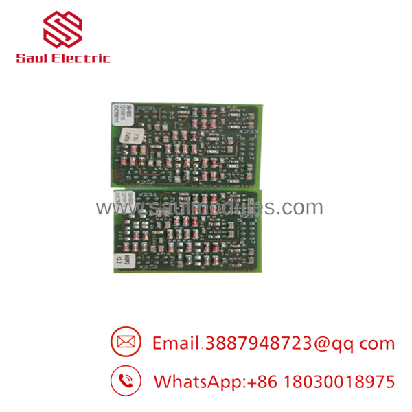
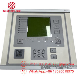
- XVC768115 3BHB007211R115
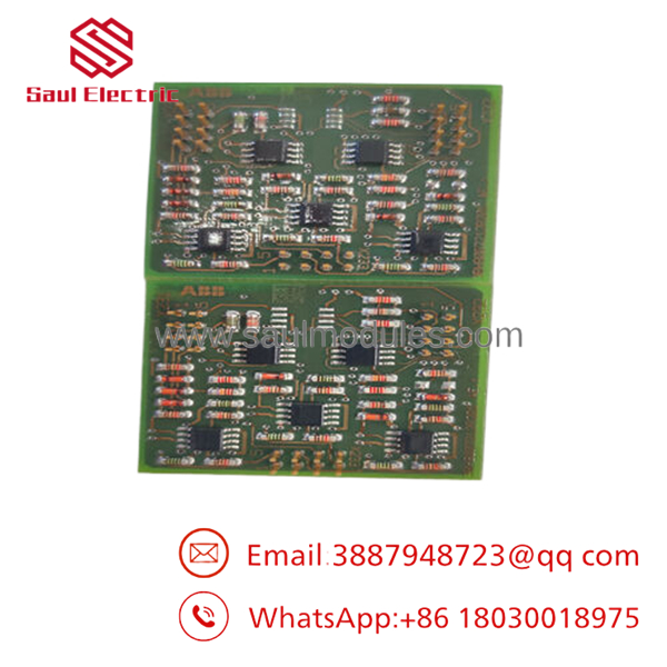
- XVC768115 3BHB007211R115
Installation & Configuration Guide
Stage 1: Pre-Installation Preparation (Estimated Time: 15 Minutes)
⚠️ Safety First
- Notify operations of the planned shutdown.
- Isolate incoming power.
- Apply Lockout/Tagout procedures.
- Wait until the DC bus is completely discharged.
- Verify zero voltage using a properly rated multimeter.
Tools Required
- Grounded ESD wrist strap
- PH1 screwdriver
- Fluke 115 or equivalent multimeter
- Wire labels
- Smartphone for documentation
Data Backup
- Save drive parameters.
- Record board location.
- Photograph every connector.
- Document hardware revision.
- Record any jumper or switch settings.
Stage 2: Removing the Old Module (Estimated Time: 10 Minutes)
- Open the drive cabinet.
- Disconnect all signal connectors carefully.
- Label every cable.
- Remove retaining screws.
- Pull the board straight from the guide rails.
- Inspect connectors and backplane for heat damage or contamination.
⚠️ Keep the original board until the replacement passes all functional tests.
Stage 3: Installing the New Module (Estimated Time: 15 Minutes)
- Wear an ESD wrist strap.
- Verify:
- Model: XVC768115
- ABB Order No.: 3BHB007211R115
- Configuration Clone (Critical)
- Confirm identical hardware revision.
- Verify connector orientation.
- Check jumper configuration if fitted.
- Ensure the board seats fully into the backplane.
- Secure mounting hardware.
- Reconnect all cables.
Self-Checklist
- Correct part number
- Board fully seated
- Connectors secured
- Hardware revision verified
- ESD precautions followed
Stage 4: Power-On & Testing (Estimated Time: 30 Minutes)
Pre-Power Inspection
- Verify auxiliary control voltage.
- Check connector alignment.
- Confirm no tools remain inside the cabinet.
Power-Up Procedure
- Apply auxiliary control power.
- Observe status LEDs.
- Verify communication with the main controller.
- Confirm current feedback values are stable.
- Start the drive at low load.
- Compare measured current with calibrated instruments.
- Monitor fault history for overcurrent or sensor errors.
⚠️ Troubleshooting Note
- Current feedback incorrect: Inspect current transformers and sensing cables.
- Board not recognized: Verify hardware revision and connector seating.
- Immediate protection trip: Check for shorted IGBTs or damaged current sensors before replacing another board.
Frequently Asked Questions (FAQ)
Q1. Can the XVC768115 be replaced while the drive remains energized?
No.
This board interfaces with the drive protection system. Even after input power is removed, hazardous DC bus voltage may remain inside the cabinet. Always verify the DC link is fully discharged before servicing.
Q2. What is the primary function of the ?
The board continuously measures system current and supplies feedback to the drive controller for regulation and protective functions. Accurate current feedback is essential for torque control, overload protection, and fault diagnostics.
Q3. Is this module still available from ABB?
Most boards available today are supplied through industrial spare-parts distributors as New Original, New Surplus, or professionally tested inventory. Availability depends on stock and the lifecycle status of the associated drive platform.
Q4. What should I verify before ordering?
Confirm:
- ABB Order Number (3BHB007211R115)
- Hardware revision
- Drive model
- Cabinet serial number
- Firmware revision
- Connector style
A visually similar board may not be compatible with every drive revision.
Q5. Why are New Surplus boards less expensive than factory pricing?
New Surplus inventory usually comes from cancelled projects, excess OEM stock, or strategic spare-part inventories. Although unused, every board should undergo serial-number verification, visual inspection, communication testing, and functional validation before shipment.
Q6. What inspections should be completed before shipment?
A complete quality process should include:
- OEM label verification
- Serial number traceability
- Visual PCB inspection
- Power-on functional testing
- Current measurement verification
- 24-hour burn-in test
- Insulation resistance test (>10 MΩ where applicable)
- Anti-static packaging with QC approval
Test reports, photos, and videos should be available upon request.
Q7. What is the most common field installation mistake?
Replacing the monitoring board without investigating the cause of the original fault.
I’ve seen drives where the current monitoring board failed because a damaged current transformer or a shorted IGBT sent abnormal signals into the circuit. Installing a new board without checking the surrounding hardware often results in another failure during the first startup. Measure the current sensors, inspect the power stage, and verify insulation before energizing the replacement board.


 Start Chat


