





Description
Product Introduction
The Nokia / Alcatel-Lucent DFP-CM-14B-2T is a specialized cellular infrastructure RF component—specifically a Duplexer Filter (DFP) module—built for Alcatel-Lucent wireless Base Transceiver Stations (BTS). Installed in macro cell site cabinets or outdoor RF front-end assemblies, this module allows high-power transmit signals and sensitive receive signals to operate simultaneously over a single antenna feedline without mutual interference.
Constructed with precision cavity resonators and copper-plated grounding structures, the DFP-CM-14B-2T provides extreme selectivity, minimal insertion loss, and high rejection of adjacent channel emissions. Its rugged metallic design ensures passive thermal dissipation and electrical stability under continuous high-power RF transmission in harsh outdoor shelter and tower environments.
Key Technical Specifications
| Parameter | Specification / Value |
| Manufacturer | Nokia / Alcatel-Lucent (ALU) |
| Model / Part Number | DFP-CM-14B-2T |
| Component Type | RF Cavity Duplexer / Filter Module |
| Application Platform | Alcatel-Lucent Macro Base Transceiver Stations (BTS) |
| Primary Function | Transmit/Receive (Tx/Rx) signal separation and out-of-band filtering |
| Enclosure Material | Heavy-Duty Machined Metal / Copper-Plated Cavity Housing |
| RF Interfaces | High-Power Coaxial Connector Terminals (e.g., 7/16 DIN or N-Type) |
| Cooling | Passive Convection (Conduction via chassis mounting) |
| Operating Temperature | Extended Outdoor Industrial Range (-40°C to +65°C) |
Application Scenarios & The “Trench” Experience
Picture this: It’s 1:30 AM during a scheduled cell tower maintenance window. A regional cellular carrier experiences elevated Bit Error Rates (BER) and dropped calls on a rural macro site due to severe intermodulation noise leaking from a high-power transmit amplifier into the sensitive receive path. Inspection reveals a degraded RF duplexer filter. Swapping in a verified DFP-CM-14B-2T cavity filter restores sharp frequency isolation between the Tx and Rx bands, dropping noise floor levels and clearing receiver desensitization across the sector in minutes.
- Macro Cell Site Base Stations – Connects power amplifiers and low-noise amplifiers (LNAs) to shared sector antennas over a single coaxial feeder.
- Co-Located Frequency Sites – Rejects adjacent carrier signals in high-density multi-operator cell towers where RF congestion causes intermodulation.
- Cellular Network Overhauls & Legacy Maintenance – Provides direct OEM hardware replacements for legacy Alcatel-Lucent BTS cabinets operating in active 3G/4G network footprints.
Transparency SOP: Quality Assurance & Testing
Every RF duplexer module undergoes a strict bench audit prior to dispatch:
- Mechanical & Cavity Audit: Physical evaluation of copper plating, cavity tuning screws, mounting points, and coaxial port threads to ensure zero physical damage or corrosion.
- S-Parameter & Network Analyzer Test: Full sweep using a calibrated Vector Network Analyzer (VNA) to measure Insertion Loss (S21/S12) and Return Loss (S11/S22) across specified passbands.
- Tx/Rx Isolation & Rejection Test: High-frequency isolation testing to confirm maximum suppression (>80 dB) between transmit and receive frequency ports.
- Power Handling Verification: Checked for passive intermodulation (PIM) stability under rated RF input power levels.
- Anti-Static & Protective Packaging: RF ports capped with protective dust covers, unit sealed in moisture-barrier bags with desiccant, and securely packed in reinforced shipping crates.
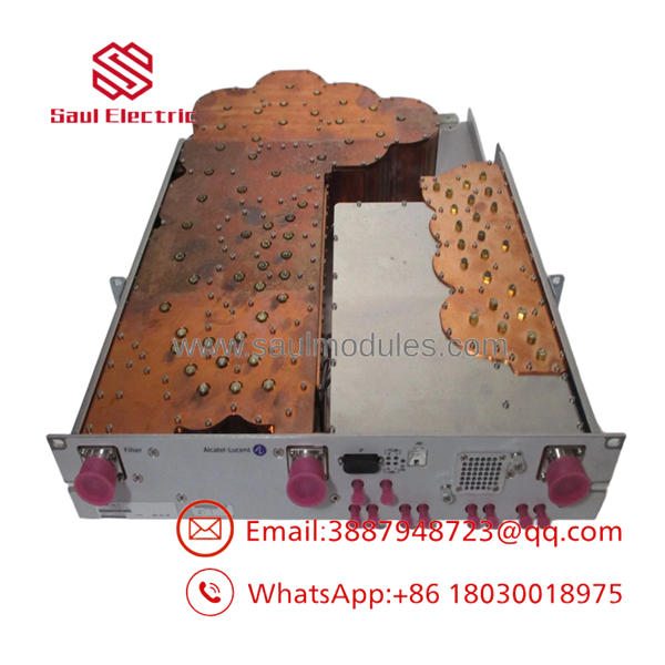
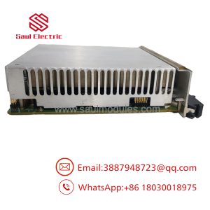
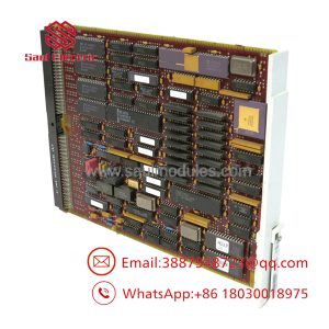
DFP-CM-14B-2T
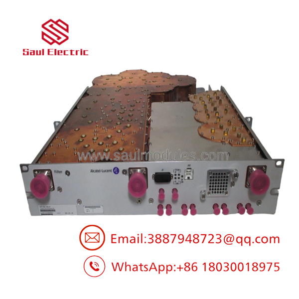
DFP-CM-14B-2T
The Veteran’s Tech Trap Guide (Crucial Value-Add)
- ⚠️ Do NOT Adjust Factory Tuning Screws!
The set screws protruding from the metallic cavity housing are factory-calibrated precision tuning elements. Tampering with or tightening these screws without an RF shield room and specialized VNA equipment will permanently de-tune the filter’s frequency response, rendering the DFP-CM-14B-2T unusable.
- ❗ Verify Coaxial Torque Specifications
When connecting RF jumpers to the DFP-CM-14B-2T ports, always use a calibrated torque wrench. Under-torqued coaxial connectors create loose ground contact and elevate Passive Intermodulation (PIM), while over-torquing damages internal pin contact surfaces.
- ⚠️ Ensure Proper Metal-to-Metal Chassis Grounding
Mount the duplexer firmly to the BTS cabinet’s ground plane. Proper chassis grounding prevents high-power RF energy from radiating into nearby control electronics and protects sensitive receiver inputs from static build-up.
- ❗ Inspect Weatherproofing on Outdoor Lines
If this module is installed in an unconditioned outdoor enclosure or tower-mounted unit (TMU), ensure all external coaxial jumper connections are sealed with weatherproofing butyl tape and UV-resistant vinyl tape to prevent moisture ingress.
Frequently Asked Questions (FAQ)
Q: What does “DFP” stand for in part number ?
A: DFP stands for Duplexer Filter Panel (or Duplexer Filter Product). It designates an RF filter assembly that combines transmit and receive paths onto a single antenna connection.
Q: Is this an active powered module or a passive RF component?
A: The is a passive RF cavity filter. It does not require active DC power wiring; it operates strictly on electromagnetic cavity resonance to filter high-frequency radio signals.
Q: Can this unit be used across any frequency band?
A: No. Cavity duplexers are factory-engineered and tuned for specific cellular frequency bands (e.g., 850 MHz, 900 MHz, 1800 MHz, or 2100 MHz). Verify that the frequency passband of the CM-14B-2T variant matches your network’s operating channel allocation.

 Start Chat


