





Description
Product Introduction & Engineering Value
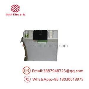
When managing complex field devices like smart motor controllers, photoeyes, pneumatics, and variable frequency drives (VFDs), running individual hardwired control loops to an SLC chassis creates wiring clutter and increases installation costs. The Allen-Bradley 1747-SDN acts as a master communication gateway on the DeviceNet network trunkline, concentrating signals from up to 63 slave nodes over a single 5-wire trunk network.
Installed in any single-slot I/O location in an SLC 500 chassis, the 1747-SDN uses M0/M1 file transfers or discrete I/O mapping to continuously pass diagnostic and control data between field devices and the CPU. Plant engineers count on the 1747-SDN for real-time device health feedback, rapid parameter updates, and streamlined wiring across large production cells.
Technical Specifications
| Specification | Parameter Value |
| Network Protocol | DeviceNet (CIP over CAN-based physical layer) |
| DeviceNet Role | Master / Scanner (supports Peer-to-Peer & Slave modes) |
| Supported Baud Rates | 125 kbps, 250 kbps, 500 kbps |
| Max Network Nodes | Up to 63 slave nodes per scanner |
| Backplane Current (5V DC) | 500 mA |
| External DeviceNet Power | 11 to 25V DC required on network connector (24V DC nominal) |
| DeviceNet Current Consumption | 90 mA max from network bus |
| Diagnostic Display | Dual 7-segment LED display (Node address & status codes) |
| Configuration Software | RSNetWorx for DeviceNet |
| Operating Temperature | 0°C to 60°C (32°F to 140°F) |
Field Application & The “Trench” Experience
During a critical shift at a high-speed packaging plant, an entire conveyor line stopped after a physical line disturbance caused a CAN transceiver fault on an older DeviceNet scanner card. The front 7-segment display on the module locked up with a scrolling error code A#75 (DeviceNet power drop/bus fault). A technician swapped in a bench-tested 1747-SDN replacement module. By uploading the saved network configuration file via RSNetWorx for DeviceNet through a 1770-KFD gateway, they restored node mapping for 18 PowerFlex drives and 12 ArmorBlock I/O modules, bringing the production line back online within 30 minutes.
- Smart Motor Control Center (MCC) Integration: Interfacing PowerFlex VFDs and E3/E3 Plus Electronic Overload Relays directly to an SLC 5/03, 5/04, or 5/05 CPU.
- Automotive Body Welding Fixtures: Scanning distributed field I/O blocks, valve manifolds, and proximity switch clusters across robotic welding cells.
- High-Speed Material Handling & Bottling Lines: Exchanging real-time barcode reader data and photoelectric sensor status without installing hundreds of individual field wires.
Transparency SOP: QA & Testing
- Connector & Physical Inspection: Checking the 5-pin open-style DeviceNet phoenix terminal, gold backplane fingers, and verifying the 7-segment diagnostic LED display matrix.
- DeviceNet Bus Power & Voltage Audit: Applying 24V DC network power to the 5-pin connector pins (V+ and V-) to confirm internal power regulation and network transceiver isolation.
- Multi-Node Scan & RSNetWorx Verification: Placing the 1747-SDN into an active SLC test rack with multiple PowerFlex drives and distributed I/O blocks; executing full scan loops via RSNetWorx across 125k, 250k, and 500k baud rates.
- Thermal Burn-In & Stress Testing: Running continuous M0/M1 file data transfers across a multi-node DeviceNet network inside an environmental test chamber for 12 hours to verify communication integrity.
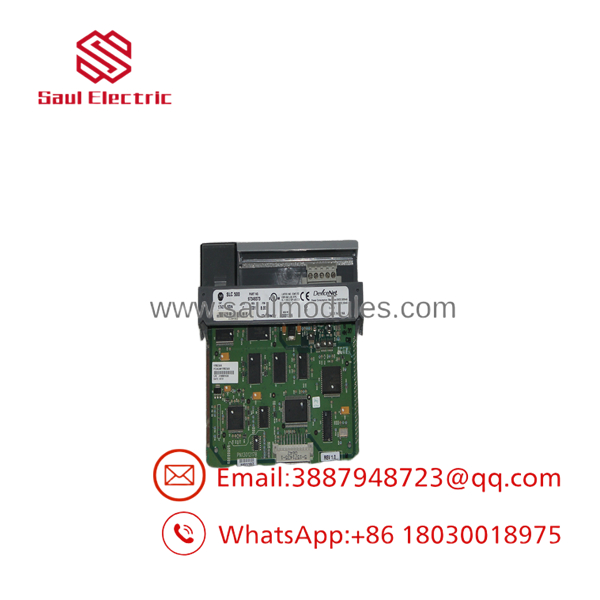
- 1747-SDN
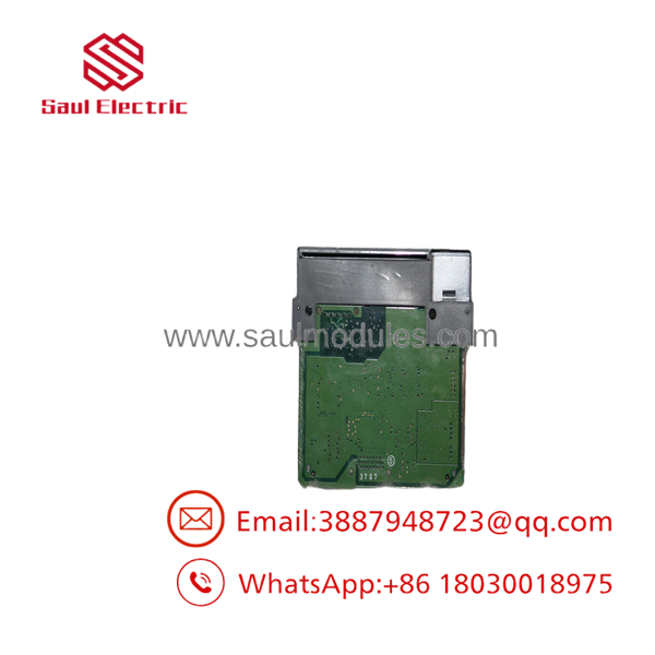
- 1747-SDN
The Veteran’s Tech Trap Guide
- ⚠️ Mandatory 24V DC External Bus Power: A common oversight is forgetting that the 1747-SDN requires external 24V DC power on its 5-pin front network connector to power its internal CAN transceivers. If the DeviceNet power supply is off or disconnected, the module’s 7-segment display will flash error codes (such as
E#91orA#75) and refuse to scan network nodes—even if the SLC chassis power supply is fully functional. - PRO TIP: Network Termination Resistors: DeviceNet is a CAN-based network that strictly requires a 121 Ω, 1/4-Watt terminating resistor at each physical end of the main trunkline (between the CAN_H and CAN_L signal wires). Missing or incorrectly placed termination resistors lead to signal reflection, intermittent packet drops, and sporadic node offline errors (
E#78). - ⚠️ Matching Node Scan Maps & M0/M1 Files: The 1747-SDN stores its network scanlist internally. When replacing a module, simply inserting a new card will not work until you download the exact network scanlist file (
.dnt) into the new 1747-SDN using RSNetWorx for DeviceNet. Ensure your PLC program’s M0/M1 data file lengths match the scanner’s configured I/O image sizes.
Dynamic FAQ
Q: Can I replace a 1747-SDN without using RSNetWorx for DeviceNet software?
A: If the original scanner card is still somewhat functional, or if you have a backup of the .dnt configuration file, you must use RSNetWorx for DeviceNet (via a 1770-KFD, 1784-U2DN, or passthrough driver) to download the scanlist and node parameters to the replacement module.
Q: Where can the 1747-SDN module be installed in an SLC chassis?
A: The 1747-SDN can be installed in any available slot in a standard 1746 SLC chassis, except Slot 0 (which is reserved for the CPU or remote adapter).
Q: What do the numbers on the front 7-segment display mean?
A: The 7-segment display alternates between showing the scanner’s own DeviceNet node address (e.g., 00) and active status or error codes. For example, code 78 indicates a missing slave node, while code 91 points to a bus-off network fault.
Q: Are replacement 1747-SDN modules fully tested prior to dispatch?
A: Yes. Every unit undergoes live DeviceNet network scanning, 24V DC bus power verification, RSNetWorx configuration loading, and continuous backplane data transfer testing on an active SLC test rack.

 Start Chat


