





Description
Product Introduction & Engineering Value
The Allen-Bradley 1756-HSC is a specialized high-speed counter module designed for ControlLogix applications that require ultra-fast signal processing beyond the scan rate capabilities of standard discrete inputs. Supporting pulse frequencies up to 1 MHz, the 1756-HSC interfaces directly with incremental quadrature encoders, pulse transmitters, flow meters, and optical sensors.
Equipped with 4 onboard high-speed outputs, the 1756-HSC can trigger immediate output actions directly on the hardware level when user-defined counter presets or window comparisons are reached. This offloads time-critical positioning, metering, and high-speed packaging tasks from the main ControlLogix CPU, ensuring microsecond-level response times and precise, repeatable motion or flow tracking.
Technical Specifications
| Specification | Parameter Value |
| Module Type | High-Speed Counter / Quadrature Encoder Interface |
| Number of Channels | 2 Counter Channels (A, B, Z per channel) or 4 Rate Measurement Channels |
| Max Input Frequency | 1.0 MHz (5V DC TTL) / 500 kHz (12–24V DC) |
| Supported Input Types | 5V DC TTL (Differential/Single-Ended), 12–24V DC (Differential/Single-Ended) |
| Onboard Outputs | 4 High-Speed Sourcing Outputs (10 to 31.2V DC, 0.5A per point) |
| Operating Modes | Counter, Frequency/Rate Measurement, Encoder/Quadrature (X1, X2, X4) |
| Backplane Current (5.1V DC) | 300 mA |
| Backplane Current (24V DC) | 3.0 mA |
| Power Dissipation | 5.6 Watts |
| Removable Terminal Block (RTB) | 1756-TBCH or 1756-TBS6H |
| Operating Temperature | 0°C to 60°C (32°F to 140°F) |
Field Application & The “Trench” Experience
On a high-speed rotary bottling and capping machine, a standard DC input module failed to accurately capture bottle-count pulses from an optical line sensor, causing missed fills whenever the line ramped up to maximum speed. Integrating a 1756-HSC module resolved the issue instantly: configured in Encoder Quadrature mode, the card tracked position down to the millimeter regardless of CPU scan fluctuations.
During a maintenance replacement of a damaged counter module, technicians used the pre-wired 36-pin 1756-TBCH removable terminal block. By unclipping the existing terminal housing, inserting the bench-tested 1756-HSC replacement into the ControlLogix chassis, and snapping the RTB back into place, line wiring remained completely untouched—allowing the system to re-zero and resume production within 10 minutes.
- High-Speed Rotary Packaging Lines: Tracking bottle/can positioning and triggering high-speed reject actuators via onboard direct outputs.
- Flow Metering & Totalizing: Summing high-frequency turbine or oval gear flow meter pulses in continuous chemical blending skids.
- Web Handling & Shearing: Measuring material length via incremental rotary encoders to control flying shears or print registration marks.
Transparency SOP: QA & Testing
- Terminal Pin & Front Display Audit: Inspecting the 36-pin RTB alignment guides, status LEDs, module latching mechanism, and backplane gold edge contacts.
- Frequency Generator Input Test: Injecting 100 kHz, 500 kHz, and 1 MHz square wave pulses into both Channel A and Channel B (5V DC and 24V DC levels) to verify counting accuracy and zero pulse drops.
- Onboard High-Speed Output Verification: Testing direct hardware output triggers (Out 0–3) by driving counter values past configured target presets under simulated operational loads.
- Thermal Chamber Burn-In: Running full dual-channel quadrature encoder counting at maximum frequency in a 60°C test chamber for 12 hours while monitoring power dissipation and signal noise immunity.
The Veteran’s Tech Trap Guide
- ⚠️ Voltage Level Configuration jumpers / Wiring: The 1756-HSC supports both 5V DC TTL and 12–24V DC input signals. Connecting 24V DC field signals to the 5V TTL terminal pins will permanently damage the module’s input optocouplers. Always double-check encoder operating voltages and wire strictly to the corresponding terminal block pins (e.g.,
A0-5VvsA0-24V). - PRO TIP: Quadrature Multiplier Selection (X1, X2, X4): In Studio 5000 / RSLogix 5000, setting the encoder evaluation mode to X4 quadruples your encoder resolution by counting every rising and falling edge on both Channel A and Channel B. Ensure your velocity/position calculation logic accounts for this 4x pulse multiplication factor.
- ⚠️ Signal Noise & Shielded Twisted Pair Wiring: High-frequency pulse inputs are highly susceptible to electrical noise from nearby VFD output cables. Always use individually shielded twisted-pair cable for encoder signals and ground the drain wire at one end only (typically at the PLC chassis grounding bus) to prevent ground loop noise from introducing ghost counts.
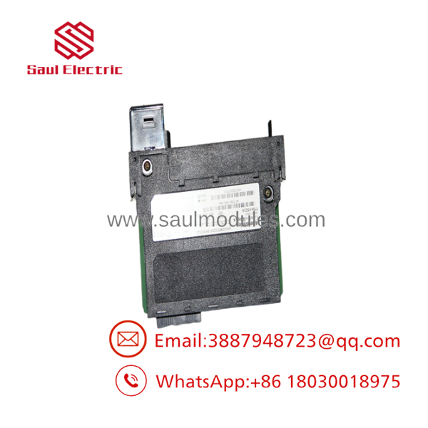
- 1756-HSC
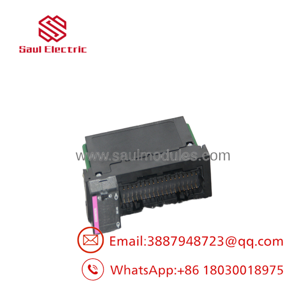
- 1756-HSC
Dynamic FAQ
Q: Can I use single-ended encoders with the 1756-HSC, or must they be differential?
A: The 1756-HSC supports both single-ended and differential encoder wiring configurations for both 5V DC and 12–24V DC signal levels.
Q: Do I need a separate output card to trigger fast actions based on count value?
A: No. The 1756-HSC features 4 onboard, high-speed sourcing outputs that can be programmed to trigger directly on counter match events within microseconds, bypassing CPU scan delays entirely.
Q: Which removable terminal block (RTB) does the 1756-HSC require?
A: The module requires a 36-pin terminal block—either the 1756-TBCH (cage-clamp) or 1756-TBS6H (spring-clamp).
Q: Are replacement 1756-HSC modules fully tested prior to shipping?
A: Yes. Every 1756-HSC card undergoes frequency generator injection testing up to 1 MHz, onboard output load checks, signal level isolation verification, and 12-hour thermal chamber burn-in.


 Start Chat


