





Description
Product Introduction & Engineering Value
The 1756-RM sits between two ControlLogix chassis and handles the redundancy communication required to maintain a primary/secondary controller architecture. It occupies one chassis slot and uses dedicated fiber-optic redundancy cables rather than an ordinary Ethernet switch connection. Rockwell specifies a maximum communication rate of 100 Mbps for the 1756-RM.
This is a legacy redundancy component, so replacement work needs to be handled as a paired-system job. The two partner redundancy modules must have the same catalog number, and Rockwell’s documentation specifically requires direct end-to-end fiber connections between the partner modules.
Technical Specifications
| Specification | 1756-RM |
|---|---|
| Module type | ControlLogix Redundancy Module |
| Supported controller families | ControlLogix 5560, 5570 |
| Communication rate | Up to 100 Mbps |
| Application | Controller/chassis redundancy |
| Required quantity | 2 per redundant chassis pair |
| Mounting | ControlLogix chassis |
| Slot width | 1 slot |
| Module location | Any chassis slot |
| 5.1 VDC current draw | 1.2 A |
| 24 VDC current draw | 120 mA |
| 1.2 VDC current draw | 4 mA |
| Maximum power dissipation | 9.0 W |
| Thermal dissipation | 31 BTU/hr |
| Operating temperature | 0 to 60 °C (32 to 140 °F) |
| Approximate weight | 0.29 kg (0.64 lb) |
| Enclosure | Open-style |
| Temperature code | T4 |
Rockwell’s current ControlLogix technical data provides these electrical, environmental, and mechanical specifications for the 1756-RM.
Redundancy Cable Options
The 1756-RM uses dedicated 1756-RMC redundancy cables:
- 1756-RMC1 — 1 m (3.28 ft)
- 1756-RMC3 — 3 m (9.84 ft)
- 1756-RMC10 — 10 m (32.81 ft)
These cables are specified by Rockwell for connecting partner redundancy modules.
Field Application & The “Trench” Experience
Consider a continuous process where two ControlLogix chassis are configured as a redundant controller pair. During a planned maintenance shutdown, one 1756-RM begins reporting a redundancy fault. The controller itself is still available, but the redundancy pair can no longer maintain its expected state.
The maintenance technician does not simply swap one module and walk away. The first checks include the RM catalog number, Series, firmware revision, redundancy cable, partner module, chassis slot, and controller compatibility. After replacement, the pair is allowed to re-establish communication and complete qualification before the system is returned to normal operation.
That sequence matters. A redundancy system can appear electrically healthy while still failing to qualify as a valid redundant pair.
Specific application scenarios
- Continuous process control where redundant ControlLogix 5570 controllers protect against processor or chassis failure.
- Boiler and utility control systems where controller availability is important during uninterrupted operation.
- Large material-handling systems using paired ControlLogix chassis to maintain control availability during controller faults.
- Legacy process skids built around ControlLogix 5560/5570 redundant architectures.
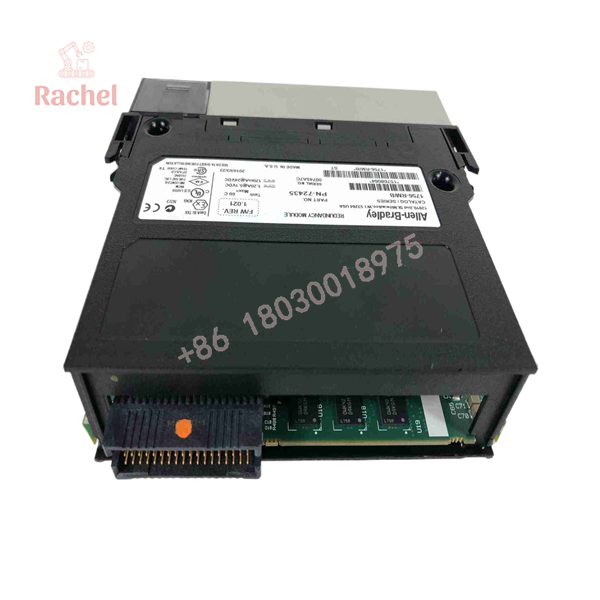
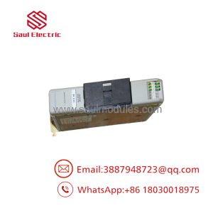
1756-RM
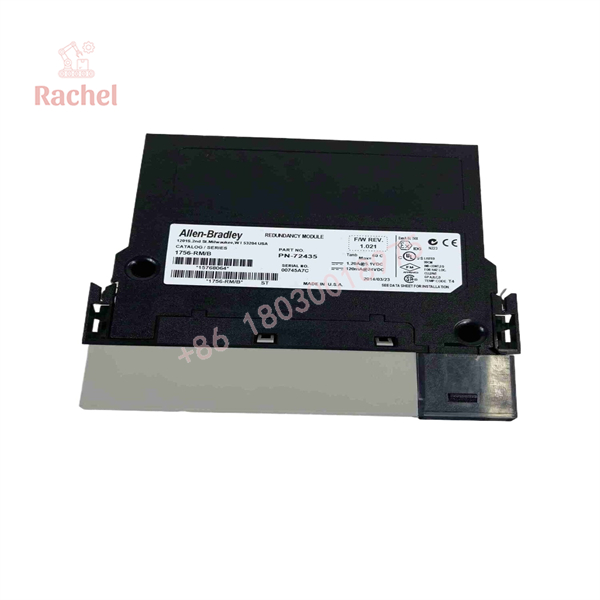
1756-RM
Transparency SOP: QA & Testing
For New Surplus or Refurbished 1756-RM inventory, testing should focus on both the module and its redundancy function.
1. Identity verification
Confirm the exact catalog number, Series, label information, and firmware revision.
2. Physical inspection
Inspect the fiber-optic port, chassis connector, housing, front indicators, and mechanical locking features.
3. Chassis power-up
Install the module in a compatible ControlLogix test chassis and verify expected startup behavior.
4. Communication test
Connect a compatible partner 1756-RM through an appropriate 1756-RMC cable and verify redundancy-module communication.
5. System qualification test
Where a complete test rack is available, verify that the redundant chassis pair can establish the expected redundancy state.
6. Final QA record
Record the tested catalog number, Series, firmware revision, and test result before shipment.
A visual inspection alone is not enough for this component. The useful test is whether the RM can participate correctly in a redundant chassis pair.
The Veteran’s Tech Trap Guide
⚠️ Trap #1 — Buying one RM when the application needs a matched pair.
Rockwell states that a pair of redundancy modules is required. The partner modules must have the same catalog number.
⚠️ Trap #2 — Connecting the fiber through a network switch.
Don’t. Rockwell specifically requires a direct, end-to-end connection between the fiber ports of the partner redundancy modules. The redundancy fiber ports are not intended to be routed through a Stratix switch or another network device.
⚠️ Trap #3 — Ignoring firmware compatibility.
The 1756-RM has multiple firmware revisions. Rockwell’s compatibility database currently lists Series B firmware through revision 3.004, with earlier versions also available.
PRO TIP: When troubleshooting a redundant ControlLogix system, record the status and firmware of both RMs and both controllers before replacing anything. Replacing only the visibly faulted component can obscure the actual redundancy qualification problem.
Dynamic FAQ
What does the 1756-RM do?
The 1756-RM links the two chassis in a ControlLogix redundant system and allows the partner redundancy modules to monitor system events and initiate redundancy responses.
How many 1756-RM modules are required?
A standard redundant chassis pair requires two 1756-RM modules—one in each chassis. Rockwell requires the partner modules to have the same catalog number.
Which controllers support the 1756-RM?
Rockwell’s technical documentation identifies the 1756-RM for ControlLogix 5560 and ControlLogix 5570 controller families.
What fiber cable does the 1756-RM use?
Rockwell specifies the 1756-RMC1, 1756-RMC3, and 1756-RMC10 cables, corresponding to 1 m, 3 m, and 10 m lengths.
Can I replace a 1756-RM with a newer RM2 or RM3?
Do not treat them as automatic drop-in substitutions. The supported controller family, redundancy-system revision, firmware, cabling, and system architecture must be checked. Rockwell’s current redundancy documentation lists different supported modules for different controller generations.
How do I verify New Surplus authenticity?
Check the Allen-Bradley catalog number, Series, serial/label information, and physical condition, then compare the module identification with Rockwell documentation. For a redundant system, also verify that the replacement is compatible with the existing partner module.
What warranty applies to a 1756-RM?
For New Surplus or Refurbished inventory, warranty terms depend on the supplier and should be confirmed in writing. Do not represent an aftermarket warranty as Rockwell Automation’s manufacturer warranty. Rockwell’s current documentation should be used to verify the product’s technical identity and lifecycle information.

 Start Chat


